
Surface-treated fluorescent material and process for producing surface-treated fluorescent material

a technology of surface-treated fluorescent materials and fluorescent materials, which is applied in the direction of luminescent compositions, chemistry apparatuses and processes, transportation and packaging, etc., can solve the problems of degradation of properties of silicate phosphors having alkaline earth metal elements, emission intensity or color tone change, poor durability, etc., to prevent decomposition and deterioration, excellent moisture resistance, and no degradation of brightness

Inactive Publication Date: 2013-06-27
SEKISUI CHEM CO LTD
View PDF7 Cites 2 Cited by
  • Summary
  • Abstract
  • Description
  • Claims
  • Application Information

AI Technical Summary

Benefits of technology

The present invention provides a surface treated phosphor that is resistant to moisture and can maintain its brightness and color tone even after long periods of use or exposure to high temperatures and humidity. The method of production is efficient and economical as it does not require an expensive reactor and can be carried out in an aqueous solution.

Problems solved by technology

However, surfaces of such silicate phosphors having an alkaline earth metal element are easily decomposed and deteriorated by moisture or water in the air.
For this reason, long-term use of the silicate phosphors in the air tends to cause a reduction in emission intensity or a change in color tone, leading to a degradation of properties as phosphors and poor durability.
However, it is difficult to completely disperse powdered phosphor particles by the vapor phase method disclosed in Patent Literatures 3 and 4.
Therefore, it is difficult in practice to cover the entire surface of each phosphor particles evenly, and pinholes, unevenness of the covering, and the like are likely to be generated.
Further, a vapor phase method is problematic because it is usually performed at high temperature of 400° C. or higher, resulting in a remarkable degradation of fluorescence properties after treatment depending on the type of phosphors.
In addition, large-scale apparatus is needed for the method, leading to increased production costs.
However, since a metal alkoxide, which is a starting material, usually has high reactivity, it is very difficult to control reaction conditions for allowing a hydrolysis reaction to be carried out only on the surfaces of phosphor particles.
Further, the covering method disclosed in Patent Literature 5 is problematic in view of reaction efficiency and costs because a hydrolysis reaction is carried out in the presence of a large amount of aqueous ammonia, so that almost all raw materials undergo a reaction to be consumed in a solution, not on the surfaces of phosphor particles.
In addition, phosphors may be hydrolyzed to deteriorate during treatment because of the large amount of aqueous ammonia.
However, improvement in moisture resistance is hardly observed in practice.
Further, reaction conditions disclosed in Examples of Patent Literature 6 are problematic because a covering reaction hardly occurs on the surfaces of phosphor particles.
Even if part of the surface is covered, it is difficult for particulate covering to efficiently block moisture.
The method disclosed in Patent Literature 7 is problematic in view of efficiency and costs because a long-term reaction and precise control of temperature and processes are needed.
In the neutralization sedimentation method disclosed in Patent Literature 8, it is difficult in practice to deposit a covering material on the surfaces of phosphor particles as a continuous film.

Method used


Image

  • Surface-treated fluorescent material and process for producing surface-treated fluorescent material
  • Surface-treated fluorescent material and process for producing surface-treated fluorescent material
  • Surface-treated fluorescent material and process for producing surface-treated fluorescent material

Examples


example 1

[0166]As a phosphor matrix, a green silicate phosphor (25 g) with a median particle size (D50) of about 16 μm (main component: (Sr,Ba)2SiO4:Eu2+, emission wavelength: 529 nm) was added to a mixed aqueous solution (500 ml) including 0.1 mol / L ammonium fluorotitanate ((NH4)2TiF6) and 0.1 mol / L boric acid. The resulting mixture was stirred to sufficiently disperse the phosphor and the reaction was carried out at 35° C. for two hours. After the reaction, the mixture was subjected to filtration and rinsing to collect the phosphor. The resulting phosphor was vacuum dried at 120° C. for one hour to give a surface treated phosphor.

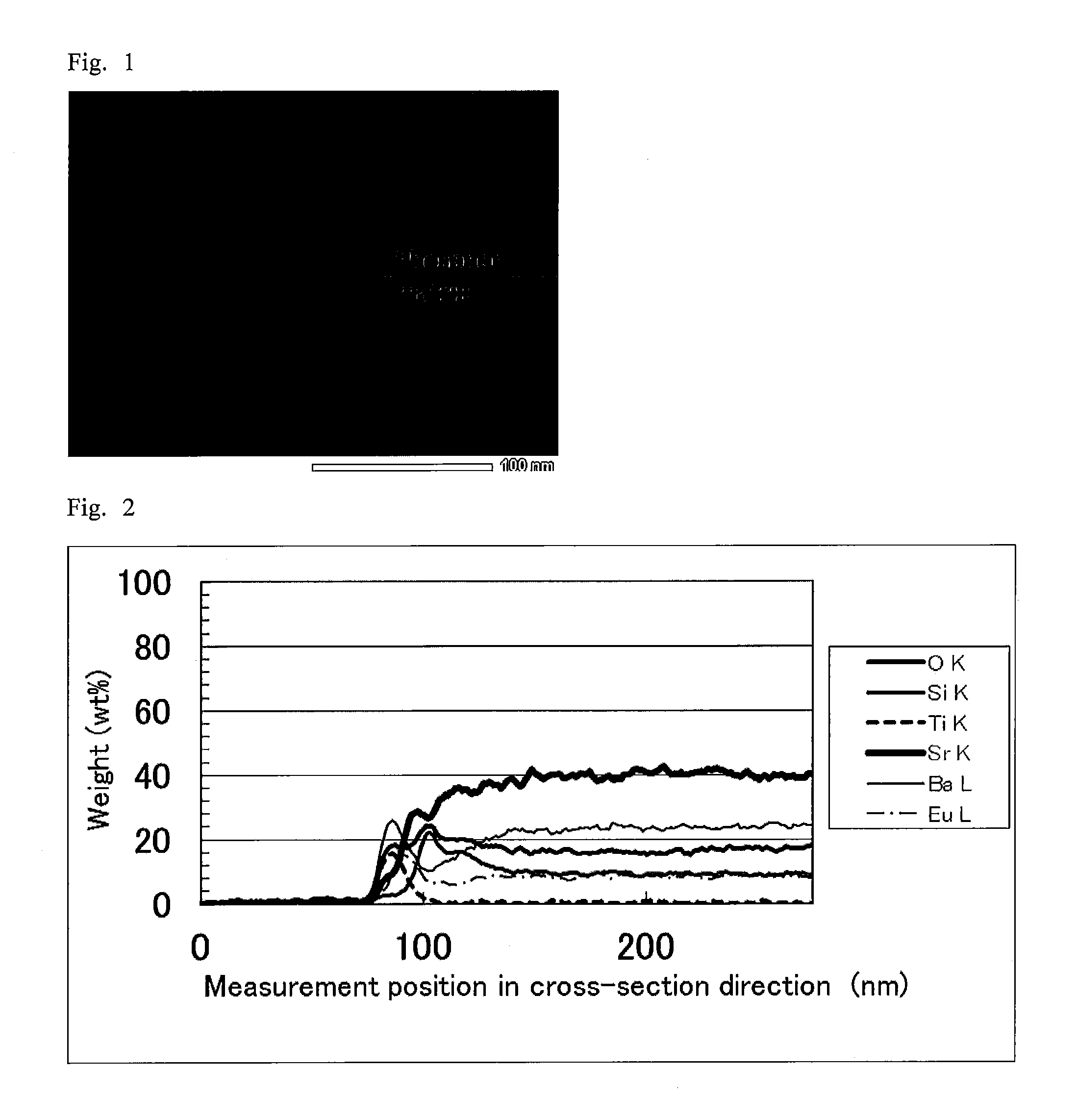
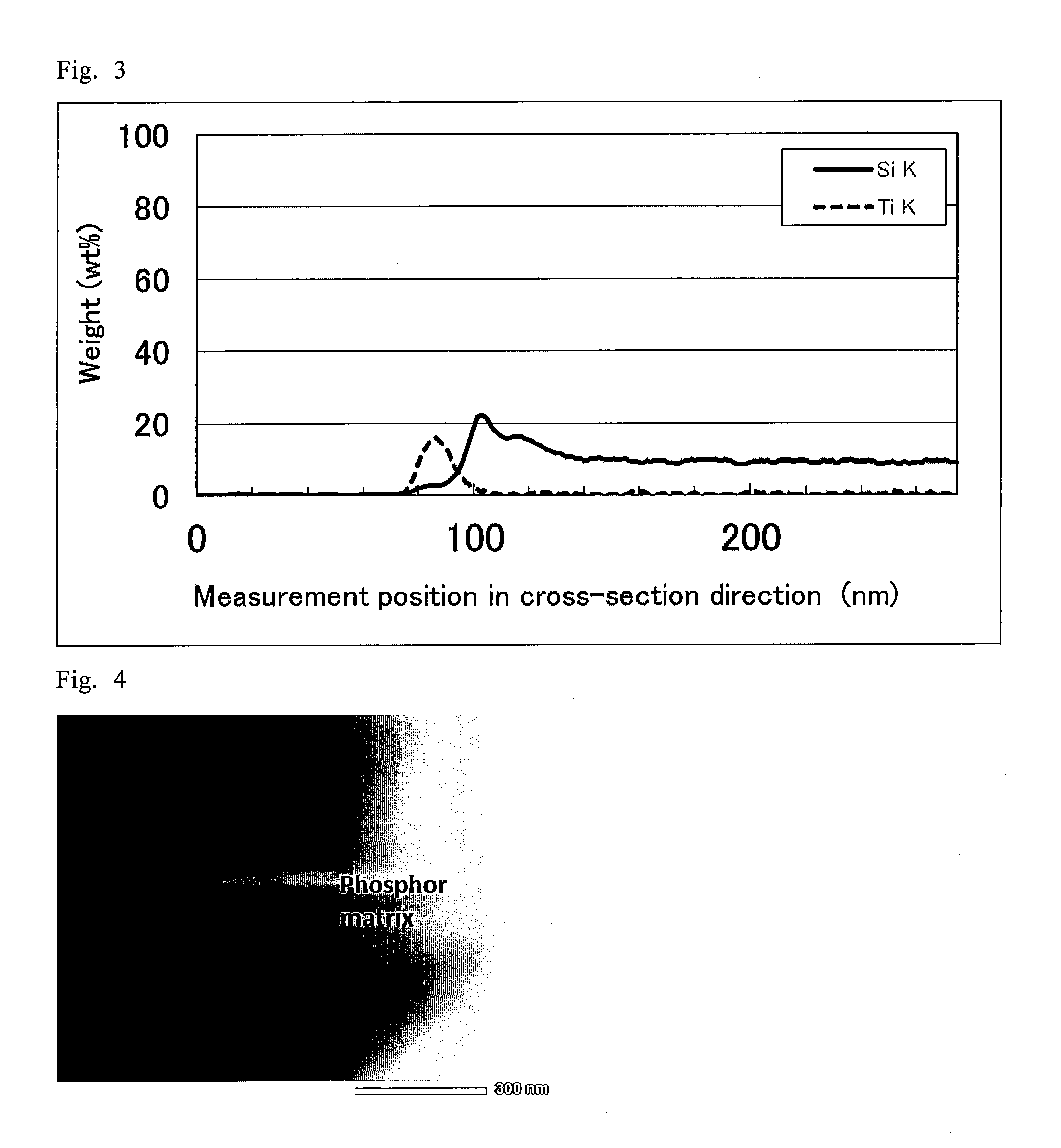
[0167]“Measurement of thickness of covering layer and elemental composition analysis in the cross-sectional direction” were performed on the resulting surface treated phosphor by the following method.

[0168]The results show that an about 53-nm-thick surface treatment layer is formed on the surface of each phosphor matrix.

[0169]With respect to the surface treated ph...

example 2

[0175]As a phosphor matrix, a green silicate phosphor (25 g) with a median particle size (D50) of about 16 μm (main component: (Sr,Ba)2SiO4:Eu2+, emission wavelength: 529 nm) was added to an aqueous solution (500 ml) including 1.0 mol / L ammonium fluorotitanate ((NH4)2TiF6). The resulting mixture was stirred to sufficiently disperse the phosphor and the reaction was carried out at 35° C. for 10 minutes. After the reaction, the mixture was subjected to filtration and rinsing to collect the phosphor. The resulting phosphor was vacuum dried at 120° C. for one hour to give a surface treated phosphor.

[0176]“Measurement of thickness of covering layer and elemental composition analysis in the cross-sectional direction” were performed on the resulting surface treated phosphor by the same method as Example 1. The result showed that an about 214-nm-thick surface treatment layer was formed on the surface of the phosphor matrix.

[0177]The elemental composition analysis in the cross-sectional dire...

example 3

[0180]As a phosphor matrix, a green silicate phosphor (2.4 g) with a median particle size (D50) of about 16 μm (main component: (Sr,Ba)2SiO4:Eu2+, emission wavelength: 529 nm) was added to a mixed aqueous solution (500 ml) including 0.05 mol / L ammonium fluorotitanate ((NH4)2TiF6) and 0.2 mol / L boric acid. The resulting mixture was stirred to sufficiently disperse the phosphor and the reaction was carried out at 35° C. for two hours. After the reaction, the mixture was subjected to filtration and rinsing to collect the phosphor. The resulting phosphor was vacuum dried at 120° C. for one hour to give a surface treated phosphor.

[0181]“Measurement of thickness of covering layer and elemental composition analysis in the cross-sectional direction” were performed on the resulting surface treated phosphor by the same method as Example 1. The result showed that an about 35-nm-thick covering layer was formed on the surface of the phosphor matrix.

[0182]The elemental composition analysis in the...


PUM

PropertyMeasurementUnit
Temperatureaaaaaaaaaa
Fractionaaaaaaaaaa
Fractionaaaaaaaaaa

Abstract

Provided are a surface treated phosphor having high dispersibility and remarkably improved moisture resistance without degradation in fluorescence properties, and a method of producing the surface treated phosphor.The present invention relates to a surface treated phosphor including: a phosphor matrix including an alkaline earth metal and silicon; and a surface treatment layer including an alkaline earth metal, silicon, and a specific element belonging to groups 4 to 6 of the periodic table, wherein, when element distribution of the surface treatment layer in the thickness direction viewed in cross-section is determined by electron microscopy and energy dispersive X-ray spectroscopy coupled with the electron microscopy, the position representing the maximum peak of a specific element content is located closer to the surface than the position representing the maximum peak of a silicon content and silicon contents of the phosphor matrix and the surface treatment layer satisfy the following formula (1):[Formula 1]S1<S2  (1)wherein S1 represents the silicon content of the phosphor matrix and S2 represents the silicon content of the surface treatment layer.

Description

TECHNICAL FIELD[0001]The present invention relates to a surface treated phosphor with remarkably improved moisture resistance and a method of producing the surface treated phosphor.BACKGROUND ART[0002]Recently, semiconductor light-emitting devices emitting white light (white LEDs) have attracted attention as next-generation light sources due to their advantages such as low power consumption, high efficiency, eco-friendliness, and long life.[0003]In order to produce white light with white LEDs, a blue or ultraviolet LED is commonly combined with phosphors (red, yellow, green phosphors, and the like) which can be excited by light of such LEDs.[0004]Silicate (also referred to as silicate salt) phosphors having an alkaline earth metal element easily provide a wider range of emission wavelength which is obtained by composition control and have high luminous efficiency and the like. Therefore, such silicate phosphors attracted attention due to their characteristics. Particularly, typical ...

Claims


Application Information

Patent Timeline
IPC IPC(8): C09K11/77H01L33/50
CPCC09K11/7734H01L33/502Y10T428/2991Y10T428/2993H05B33/14C09K11/025C09K11/77342C09K11/08C09K11/59
Inventor SUN, REN-DENAKATANI, YASUHIROOOMURA, TAKAHIRO
Owner SEKISUI CHEM CO LTD
Learn More