Circuit for transmitting ask RF signals with data signal edge adaptation

a technology of data signal edge adaptation and transmitting circuit, which is applied in the direction of modulation, high frequency amplifier, amplifier, etc., can solve the problems of reducing the efficiency of the transmitter circuit, reducing the output power in an easy manner, and limiting the bandwidth of the signals to be transmitted. , to achieve the effect of high cutoff frequency

Active Publication Date: 2013-06-27
EM MICROELECTRONIC-MARIN
View PDF6 Cites 17 Cited by
  • Summary
  • Abstract
  • Description
  • Claims
  • Application Information

AI Technical Summary

Benefits of technology

[0020]One advantage of the digital amplitude modulation transmitter circuit for RF signals lies in the fact that digital means are used to shape the data pulses and to attenuate data transition edges for the transmission of ASK data signals. This type of digital pulse shaper circuit can be implemented in several embodiments. The common feature of these embodiments is that the transition shape between two data symbols is defined by one or more wave shapes stored in the form of one or more digital value sample sequences in a memory of the circuit. By reprogramming this memory, it is easy, depending upon the use application of the transmitter circuit, to adapt the shape of the transitions between the data. The pulse shaper can for example include a raised cosine filter, which can be implemented in form of an FIR (finite impulse response) type filter.
[0021]One advantage of the data amplitude modulation transmitter circuit for RF signals lies in the fact that the power ampl

Problems solved by technology

Where a C-class output power amplifier is used for a high efficiency transmitter circuit, it is often difficult firstly to directly limit the bandwidth of the signals to be transmitted, and secondly to decrease the output power in an easy manner.
However, this type of arrangement reduces the efficiency of the transmitter circuit.
Moreover, this arrangement is generally impractical for these power amplifiers for transmitting radio frequency signals.
However, this requires a considerable number of electronic components to

Method used


Image

  • Circuit for transmitting ask RF signals with data signal edge adaptation
  • Circuit for transmitting ask RF signals with data signal edge adaptation
  • Circuit for transmitting ask RF signals with data signal edge adaptation

Examples


Embodiment Construction

[0030]In the following description, all those electronic elements of the data amplitude modulation RF transmitter circuit, which are well known to those skilled in the art in this technical field, will only be described in a simplified manner.

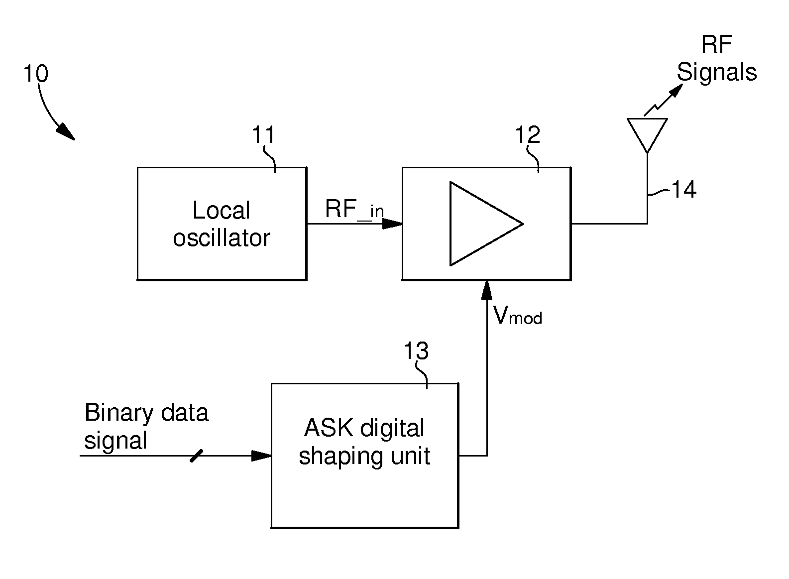
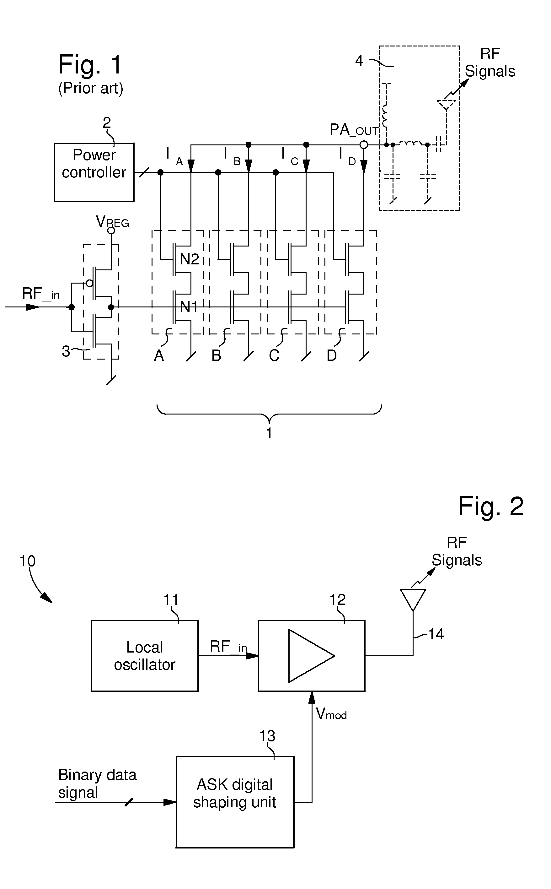
[0031]FIG. 2 shows very generally the digital amplitude modulation radio frequency transmitter circuit 10. Circuit 10 essentially includes a local oscillator 11, which may comprise a frequency synthesiser fitted with a reference oscillator connected to a quartz resonator. This reference oscillator can supply a reference signal at a frequency which may be on the order of 13.56 MHz. This local oscillator can supply at the frequency synthesiser output an oscillating signal RF_in to the input of a power amplifier 12. This oscillating signal RF_in is generated at a determined carrier frequency for the transmission of ASK RF signals by antenna 14, which is connected to the output of power amplifier 12. The carrier frequency may be selected to be 434 ...


PUM


Abstract

The circuit is provided for the transmission of data amplitude modulated radio frequency signals. The circuit includes a local oscillator for generating an oscillating signal at a determined carrier frequency, a unit for shaping data pulses to supply a data amplitude modulation control signal (Vmod), and a power amplifier receiving the oscillating signal and the data amplitude modulation control signal (Vmod) for the transmission of data amplitude modulated radio frequency signals by an antenna or an antenna arrangement. The data pulse shaping unit (13) includes a pulse shaper (21) for digitally adapting the data transition edges on the basis of an incoming digital data signal (d), and a digital-analogue conversion stage (26, 27) for converting a digital data signal shaped in the unit, in order to supply the data amplitude modulation control signal (Vmod) to the power amplifier.

Description

[0001]This application claims priority from European Patent Application No. 11194995.4 filed Dec. 21, 2011, the entire disclosure of which is incorporated herein by reference.FIELD OF THE INVENTION[0002]The present invention concerns an electronic circuit for transmitting amplitude modulated radio frequency signals, which is fitted with a means of shaping the edges of the data signals to be transmitted. The electronic circuit output includes a power amplifier connected to an antenna for transmitting ASK RF signals in a wireless communication system.BACKGROUND OF THE INVENTION[0003]Within industrial, scientific and medical applications (ISM), wireless communication systems typically use signals at the carrier frequency, which is comprised within frequency ranges reserved for such applications. The carrier frequency of these signals is generally around 434 MHz or 868 MHz.[0004]The spectral bandwidth of transmitted ASK (Amplitude Shift Keying) RF signals must, in principle, be limited ...

Claims


Application Information

Patent Timeline
IPC IPC(8): H04L27/04
CPCH04L27/04H03F1/0277H03F1/223H03F1/3241H03F3/19H03F3/245H03F3/72H03F2200/331H03F2203/7236H03F3/211
Inventor MOSER, MICHEL
Owner EM MICROELECTRONIC-MARIN
Why Eureka
Try Eureka