Computer numerical control machine tool for grinding two sides of a plane by shifting self-rotation and ultrasonic vibration

a computer numerical control machine tool and plane technology, applied in the direction of grinding machine components, manufacturing tools, lapping machines, etc., can solve the problems of deteriorating distribution uniformity of grinding speed, degrading time-variation property, heavy wear, etc., to improve machining efficiency and machining precision, improve the time-variation of grinding movement tracks, and improve the effect of machining efficiency

Active Publication Date: 2013-06-27
XIAN UNIV OF TECH
View PDF9 Cites 18 Cited by
  • Summary
  • Abstract
  • Description
  • Claims
  • Application Information

AI Technical Summary

Benefits of technology

[0012]The beneficial effects of the computer numerical control machine tool of the present invention lie in that: the workpiece assembly passively self-rotate around its center, through a moment generated by a resultant force of the grinding forces applied to the workpiece by the upper grinding plate and the lower grinding plate, and thus the separation plate only vibrates at a high frequency while the stress condition is good; the self-rotation of the workpiece assembly is a shifting self-rotation; the time variance of the grinding movement tracks is good due to the self-rotation and automatically controlled shifting; the ultrasonic vibration is applied to the separation plate, which adds a high frequency vibration to the workpiece assembly, thus the grinding speed is greatly uniformed, the distribution uniformity of the grinding speed, the machining efficiency and the machining precision can be improved, and the surface residual stress and the hardening can be reduced during a high speed grinding; and the grinding contact pressure is controlled and achieved by a moment control of the numerical control servo axis, and thus the structure is simplified.

Problems solved by technology

However, the structure of the planetary mechanism is relatively complex and the stress conditions of the separation plate (planet gear) is rather bad, resulting in a heavy wear.
One of the defects of the constant distance self-rotation lies in that the self-rotation speed of the workpiece at its self-rotation center is zero, which degrades the time-variation property.
Another defect lies in that the grinding speed at each grinding point on the surface of the workpiece equals to the sum of the rotation speed of the grinding plate and the linear velocity of the self-rotation speed of the workpiece at the grinding point, and the distribution uniformity of the grinding speed is deteriorated, because the speed at the self-rotation center of the workpiece is zero.
This kind of double surface grinding machines can partially overcome the defects of the bad track time-variation and bad uniformity of grinding speed distribution in the former grinding method, while there are still defects as follows: the sine mechanism is complex in structure, the stress condition of the separation plate is bad and the abrasion is serious, especially, the upper and lower grinding plates are fixed and only the workpiece performs a planar motion, so that the grinding speed is low, and thus the processing efficiency is low.
Till now, there is no computer numerical control machine for grinding two sides of a plane in which the upper and lower grinding plates are driven by an ultrasonic vibration apparatus to vibrate at a high frequency.

Method used


Image

  • Computer numerical control machine tool for grinding two sides of a plane by shifting self-rotation and ultrasonic vibration
  • Computer numerical control machine tool for grinding two sides of a plane by shifting self-rotation and ultrasonic vibration
  • Computer numerical control machine tool for grinding two sides of a plane by shifting self-rotation and ultrasonic vibration

Examples


Embodiment Construction

[0018]Reference will now be made in detail to the present invention in combination with drawings and the detailed embodiments.

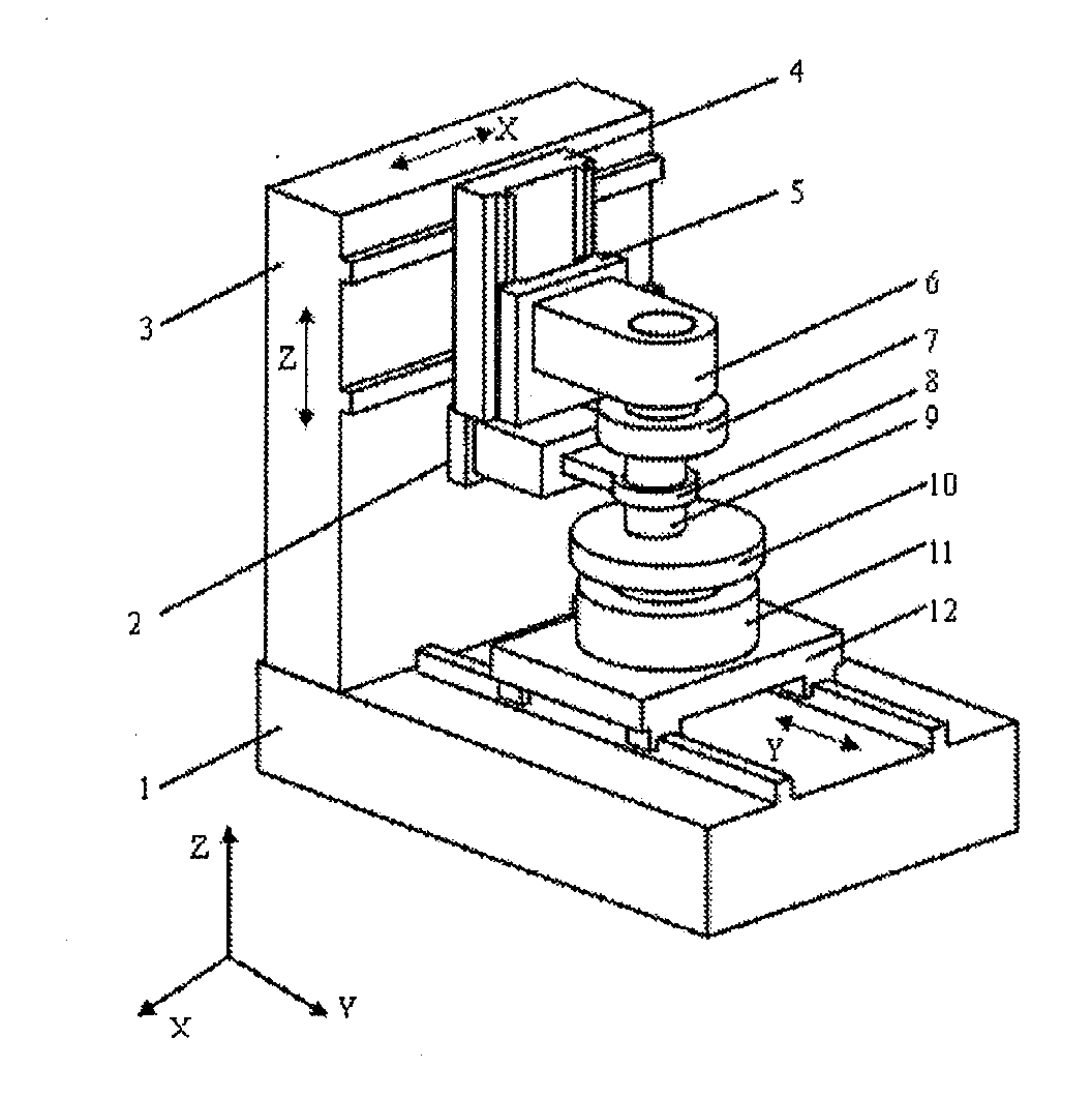
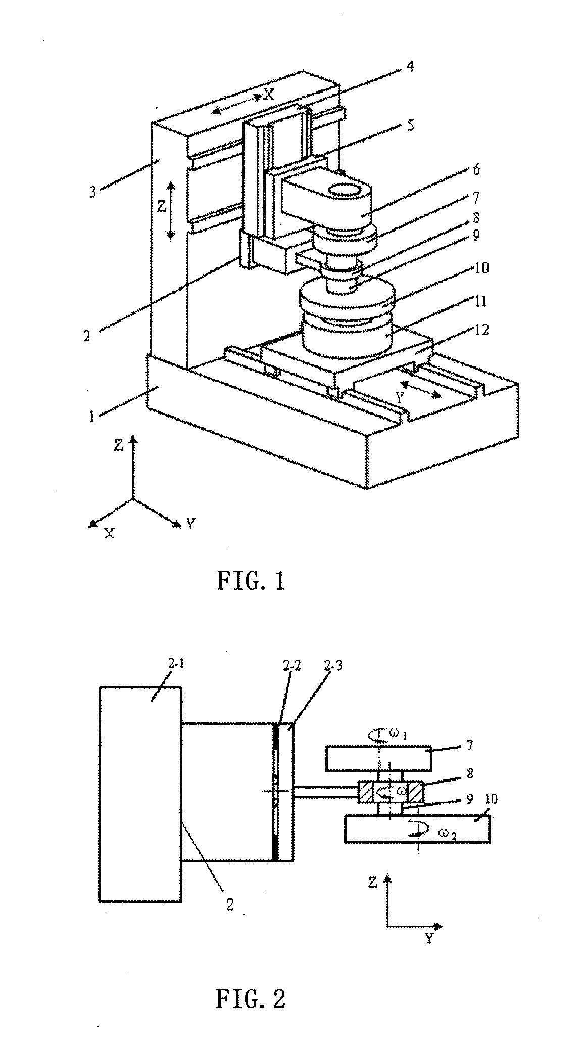
[0019]FIG. 1 shows the structure of the computer numerical control machine tool of the present invention. As shown in FIG. 1, a pillar 3 is disposed at the back portion of the tool body 1, and a Y axis movement assembly 12 is disposed on the platform of the tool body 1, a lower revolving movement assembly 11 which revolves around coordinate axis Z, is mounted on the upper surface of the Y axis movement assembly 12, a lower grinding plate 10 is coaxially mounted on the lower revolving movement assembly 11; an ultrasonic vibration assembly 2 is fixedly mounted on the pillar 3 (on the middle section thereof), and provided with a separation plate 8 for clamping a workpiece assembly 9; an X axis movement assembly 4 which moves horizontally is mounted on the the pillar 3 (on the upper section thereof), a Z axis movement assembly 5 is mounted on an upright face of t...


PUM

PropertyMeasurementUnit
shapeaaaaaaaaaa
speedaaaaaaaaaa
surface shapeaaaaaaaaaa

Abstract

A computer numerical control machine tool for grinding two sides of a plane by shifting self-rotation ultrasonic vibration, wherein a pillar (3) is provided on the tool body (1) of the machine tool, a Y axis movement assembly (12) is provided on the platform of the tool body (1), with a lower revolving movement assembly (11), which revolves about a Z coordinate axis, being mounted on the upper surface of the Y axis movement assembly (12), and a lower grinding plate (10) being mounted coaxially above the lower revolving movement assembly (11); an ultrasonic vibration assembly (2) is mounted fixedly on the pillar (3), with a separation plate (8) for clamping a workpiece assembly (9) being provided on the ultrasonic vibration assembly (2); an X axis movement assembly (4) is mounted on the upper part of the pillar (3), a Z axis movement assembly (5) is mounted on the upright face of the X axis movement assembly (4), with an upper revolving movement assembly (6), which revolves about the Z coordinate axis, being provided on the Z axis movement assembly (5), and an upper grinding plate (7) being mounted coaxially on the revolving axis of the upper revolving movement assembly (6). The present invention enhances the time variation of grinding movement tracks, the uniformity of grinding speed distribution, machining efficiency and machining precision.

Description

TECHNICAL FIELD[0001]The present invention belongs to a technical field of mechanical processing equipments, relates to a computer numerical control machine tool for grinding tow sides of a plane, and more particularly to a computer numerical control machine tool for grinding two sides of a plane by shifting self-rotation and ultrasonic vibration.BACKGROUND ART[0002]Grinding is a final finishing method of precision machining or super precision machining. The grinding methods can be classified into a loose abrasive grinding, a fixed abrasive grinding, a magnetic grinding, a vibration grinding, an electrolytic grinding, a mechanical-chemistry grinding, a magnetic fluid grinding and the like. The grinding methods can also be classified into a plane grinding and a curved surface grinding according to a surface shape of a workpiece. The plane grinding is further divided into one side grinding and two sides grinding. With respect to the two sides grinding, the workpiece is placed between ...

Claims


Application Information

Patent Timeline
Patent Type & Authority Applications(United States)
IPC IPC(8): B24B7/17B24B41/06
CPCB24B1/04B24B41/067B24B7/17B24B37/08
Inventor HUANG, YUMEIYAN, WENGAO, FENGJIANG, HAO
Owner XIAN UNIV OF TECH
Why Eureka
Try Eureka