Visual Quality Indicator for Gaseous Streams

a visual quality indicator and gaseous stream technology, applied in the nature of treatment water, vessel construction, separation process, etc., can solve the problems of ineffective prior art physical separation methods, formation of stable and pseudostable oily emulsions, and most carcinogenic effects, so as to quickly detect the presence, easy to identify the source or source of leakage, and simple and direct visual inspection

Active Publication Date: 2013-07-04
MYCELX TECH CORP
View PDF6 Cites 10 Cited by
  • Summary
  • Abstract
  • Description
  • Claims
  • Application Information

AI Technical Summary

Benefits of technology

[0027]In a further aspect, this disclosure is more generally applicable to detection of oily contaminants in any industrial process stream, where the presence of such oily elements is indeed undesired, as for example where the contaminants are indicative of a leakage. This is illustrated by the use of the invention in a heat exchanger system involving, for example, a hot process stream and a coolant stream. Oily components intended to be present in only one of the streams can, as a result of system wear and failure, leak into the other stream. The invention renders it possible to quickly detect the presence of the contaminant in the stream where it should not be present. This can be particularly

Problems solved by technology

These noxious contaminants are among the more difficult compounds to remove from water, and indeed most are carcinogenic.
The solubility of the foregoing substances renders most prior art physical separation methods generally ineffective and causes formation of stable and pseudostable oily emulsions (micelle size of 400 micrometers or less), which also do not respond well to gravity separation due to neutral buoyancy.
In the course of utilizing bilgewater filtration systems, including those based upon the foregoing principles, it is often difficult to determine the quality of effluent from oily water separators without relying on sensor readings or other means.
Moreover, it is often not possible even to determine visually if the separator unit itself is on or off.
However, the inability to perform simple visual inspections has led to accidental oily bilge water discharge and can even lead to criminal prosecution of the individuals responsible.
In the case of oily water treatment devices, it is not possible to effectively use transparent sight gauges or glass indicators on the housings or in the connecting piping, due to the tendency of the surfaces over which the discharge flows to become opaque

Method used


Image

  • Visual Quality Indicator for Gaseous Streams
  • Visual Quality Indicator for Gaseous Streams
  • Visual Quality Indicator for Gaseous Streams

Examples


Embodiment Construction

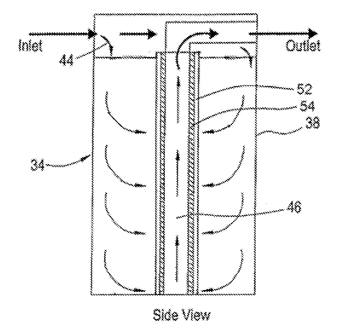
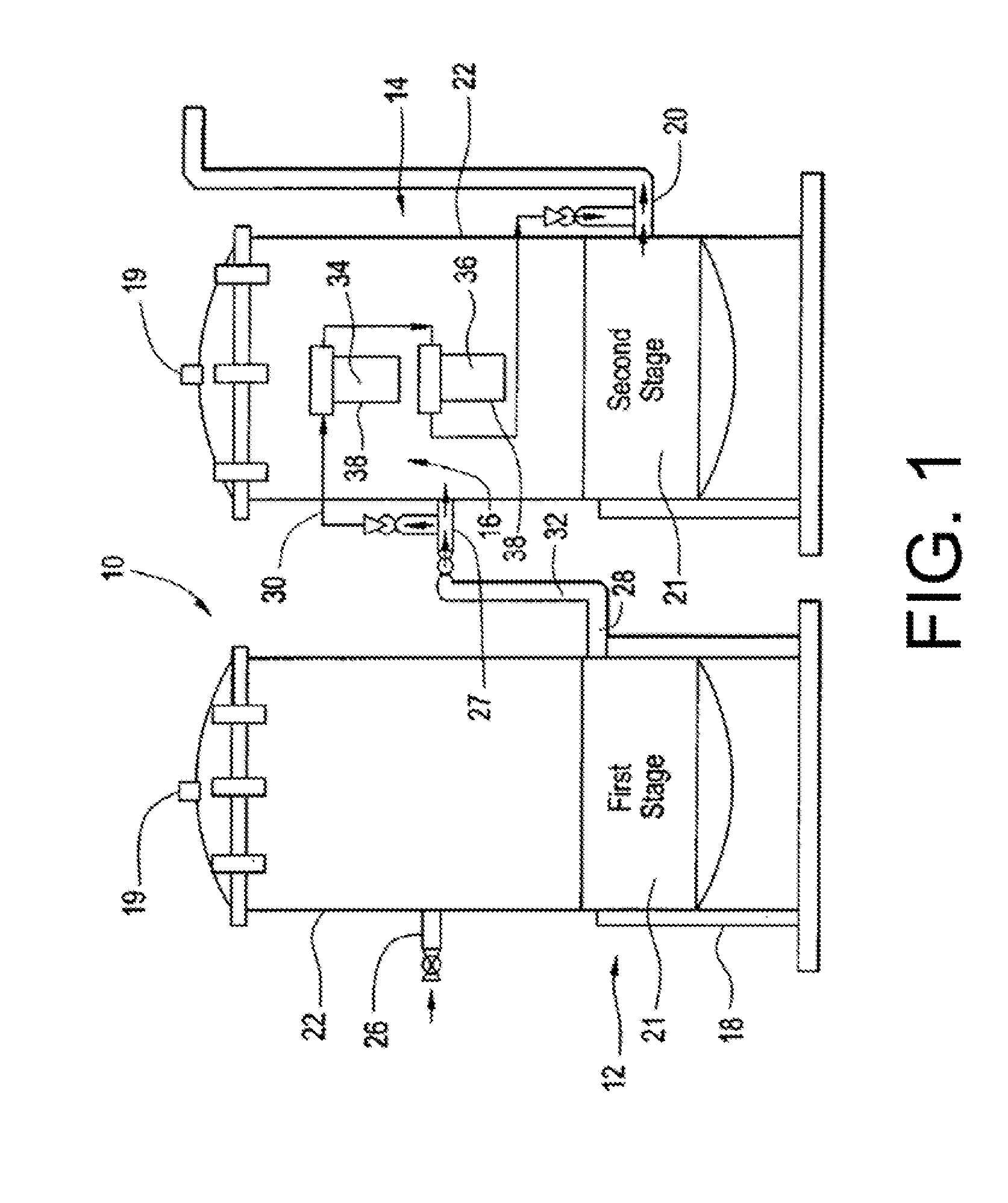
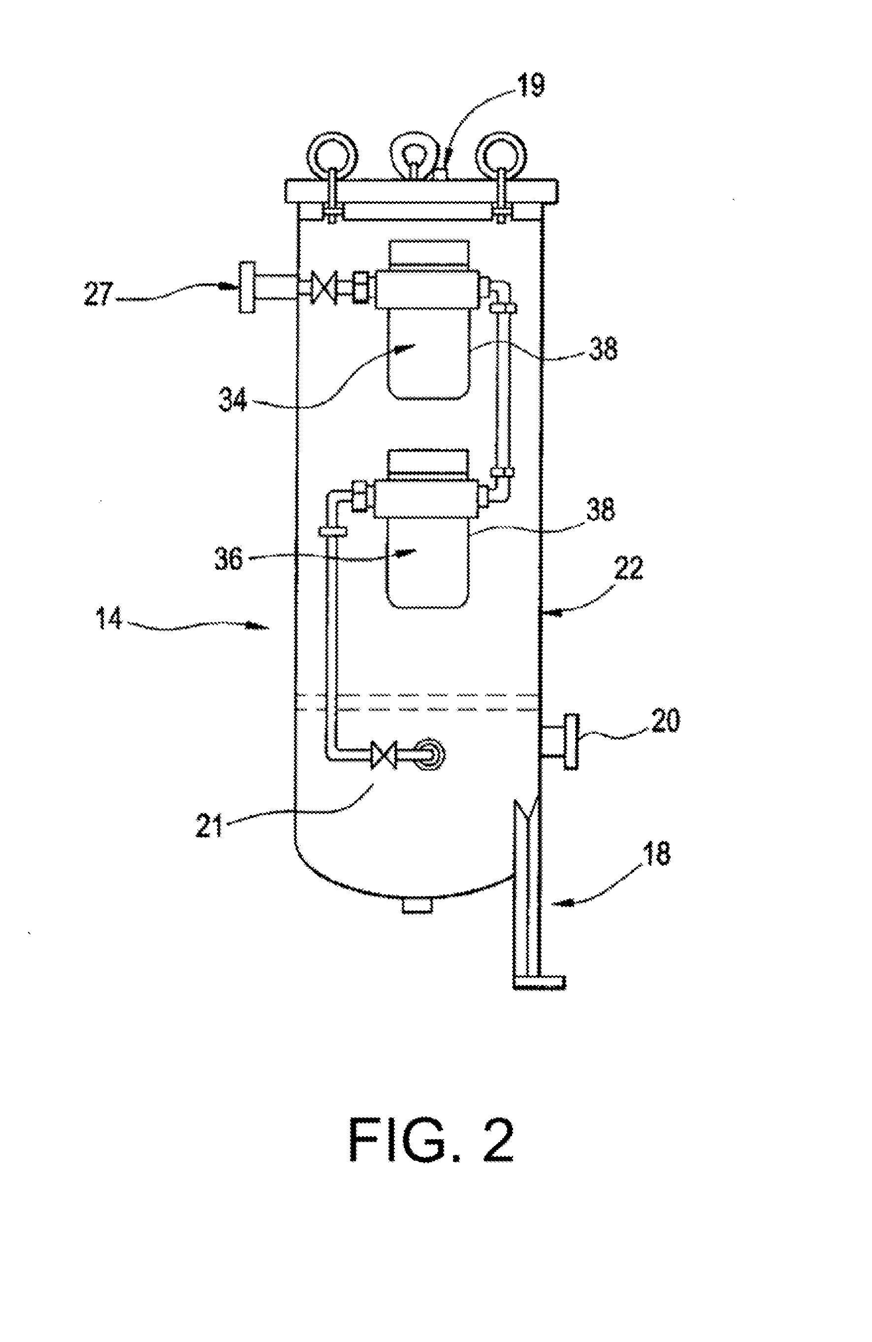
[0038]In preferred embodiments of the disclosure, a visual quality indicator device (“VQI”) is provided for determining the presence of oily contaminants in an aqueous or gaseous stream. The VQI includes a status chamber having an inlet and an outlet for receiving and discharging the stream, and a transparent wall enabling viewing of the chamber interior. A fluid-pervious filtration media is present within the chamber, which has been infused with an absorption composition comprising a homogeneous thermal reaction product of an oil component selected from the group consisting of glycerides, fatty acids, alkenes, and alkynes, and a methacrylate or acrylate polymer component; the contaminant on contact with the media being thereby immobilized. The media has a surface viewable through the transparent wall, and the stream flow path is such as to cause the stream to impinge at the media via the surface, whereby the contaminants collect selectively at said surface and are therefore highly ...


PUM

PropertyMeasurementUnit
Transparencyaaaaaaaaaa
Fluorescenceaaaaaaaaaa
Phosphorescence quantum yieldaaaaaaaaaa

Abstract

A visual indicator device and method for determining the presence of oily contaminants in a gaseous stream are provided. The device includes a filtration status chamber for receiving and discharging the gaseous stream, and a transparent wall enabling viewing of the chamber interior. A fluid-pervious filtration media within the chamber is infused with an absorption composition at which the contaminant on contact with the media is immobilized. The media has a surface viewable through a transparent wall of the filtration status chamber, and the stream flow path is such as to cause the stream to impinge at the media via the said surface, whereby the contaminants collect selectively at the media surface and are therefore highly visible through the transparent wall.

Description

CROSS-REFERENCE TO RELATED APPLICATIONS[0001]This application is a continuation-in-part application of U.S. patent application Ser. No. 13 / 475,238, filed May 18, 2012, which is a continuation application of U.S. patent application Ser. No. 12 / 079,244, filed Mar. 25, 2008, now U.S. Pat. No. 8,187,459, which claims priority from U.S. Provisional Patent Application Ser. No. 60 / 920,193, filed Mar. 27, 2007, each of which is incorporated herein by reference in its entirety.FIELD OF THE INVENTION[0002]This disclosure relates generally to an apparatus and methodology for visually determining the presence of oily contaminants suspended or dispersed in a gaseous stream, and more specifically relates to a visual indicator device for visually examining a gaseous stream to determine the presence therein of such contaminants.BACKGROUND OF THE INVENTION[0003]In the present applicant's above cited related applications and patent the invention disclosed and claimed is utilized to visually determine...

Claims


Application Information

Patent Timeline
IPC IPC(8): B01D53/18
CPCB63J4/002B63J4/006B63J4/004C02F2103/008B01D53/18C02F1/288F28F27/00
Inventor ALPER, HAL
Owner MYCELX TECH CORP
Why Eureka
Try Eureka