In particular, natural forces such as
bad weather, e.g.,
snow, ice, rain, wind, temperature, material conditions, material properties, worker competency, worker capability etc., have for many years caused accidents in the nature of falling debris which risks injury or damage to people and property in the vicinity of e.g., a
high rise building construction site.
Various safety netting systems for high-rise construction projects and the like have been provided in the past, but their implementation requirements and constraints and lack of ease of use or reconfiguration have been severe limitations in the effectiveness and efficiency of such systems.
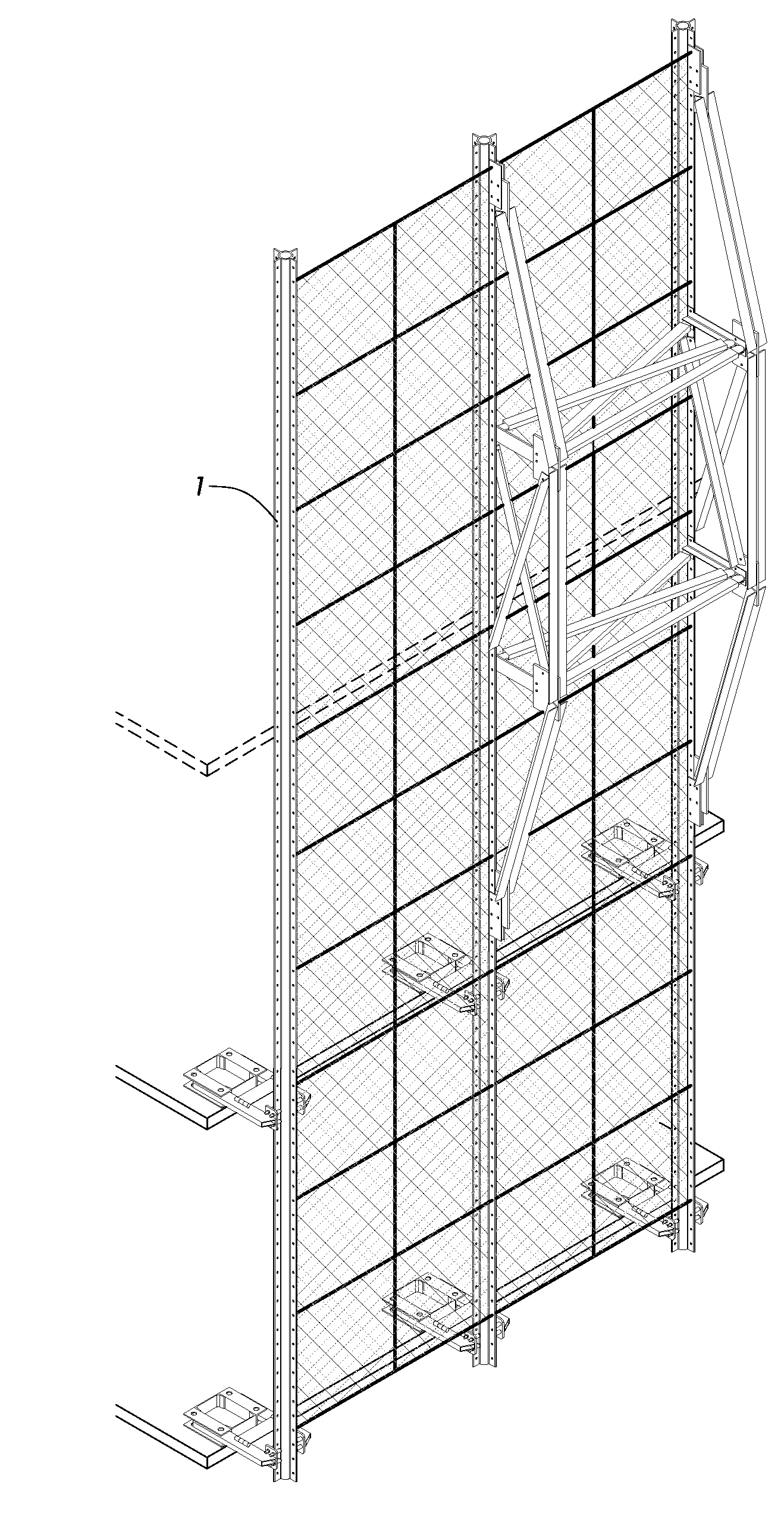
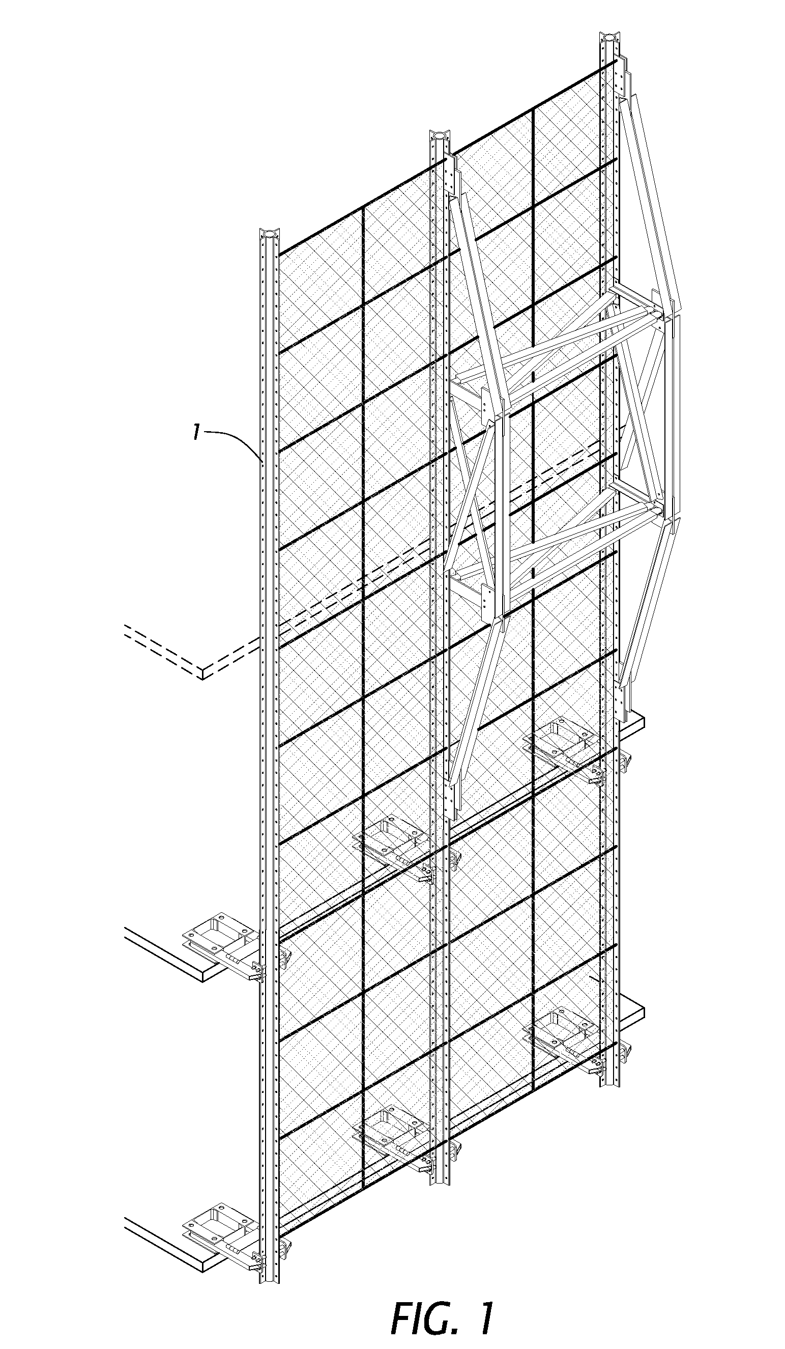
Specifically, a netting system that is substantially continuous around the periphery of the top of a building, is easily installed, is easily movable or reconfigurable during the construction process to keep pace with, and / or keep ahead of, the building construction, and is strong and lightweight, has not heretofore been available.
While typically strong, a common problem with structural systems and components for
safety barrier systems is that they are heavy, difficult to
handle, move or reconfigure and have a relatively high cost.
However, while the Dougall et al. system described in the aforementioned application appears to provide a vertical perimeter barrier at the top of a
building under construction, the description indicates that it does so in a very inefficient manner.
The vertical panels used in the Dougall et al. system appear from the description to be very large and unwieldy rigid or semi-rigid structures which would appear to be extremely difficult to move or reconfigure as the
building under construction progresses vertically as new floors are added.
Thus the barrier panels are not fixedly attached to the vertical support structural members.
The Dougall et al. system thus appears to involve a quite intricate vertical support structure which is guided by the barrier panels themselves, which panels therefore must be extremely rigid, and thus heavy or requiring a substantial amount of material, to perform the guiding function.
The Dougall et al. system fails to provide such an efficient system because it requires “dual” (i.e., corresponding) slidably engaging rigid members as opposed to a single rigid member which supports the barrier net (on one side of the net) at all times and which is slidably engaged with a
small footprint bracket which is rigidly attached to a construction
floor slab.
The Dougall et al. system is thus too heavy, expensive and cumbersome to satisfy the need for a safety netting or barrier system for optimal use in high-rise building construction projects.
However, the UBS system is heavy, difficult to
handle and is not easily reconfigurable or movable during construction.
The UBS system incorporates barrier panel support members which are engaged with vertical support members which appear to be rigidly attached to the building structure, thus requiring a substantial amount of support member
structural material.
While the UBS system described in the aforementioned document appears to provide a vertical perimeter barrier at the top of a
building under construction, the description indicates that it does so in a very inefficient manner.
The vertical panels used in the UBS system appear from the description to be very large and unwieldy rigid or semi-rigid structures which would appear to be extremely difficult to move or reconfigure as the building under construction progresses vertically as new floors are added.
The UBS system thus appears to involve a quite intricate vertical support structure which is rigidly attached to a building under construction and requires a very large amount of material.
The UBS system fails to provide such an efficient system because it requires “dual” (i.e., corresponding) slidably engaging rigid members as opposed to a single rigid member which supports the barrier net at all times and which is slidably engaged with a
small footprint bracket which is rigidly attached to a construction
floor slab, and thus has this same drawback as the Dougall et al. system discussed above.
However, no such patent or application was located in a search of USPTO or Google Patents databases.
However, to date, no such system has been provided.
Other prior systems that are directed to debris barriers for
high rise construction are lighter weight than the UBS system, but they are disadvantageous in other critical ways.
However, there is no teaching in Denny of any adjustability of the netting during the construction process.
Nor is there any teaching of a vertical netting system which substantially encloses the periphery of the top of a building under construction.
Nor is there any teaching in Denny of a structural
support system which itself is vertically adjustable via brackets attached to the floors which are already completed.
Nor does Denny et al. describe a system for enclosing the periphery of a building top with a netting system which is easily and efficiently movable or reconfigurable during the building construction process.
Nor is there any teaching in Denny et al. of providing a netting system for extending above a completed work area or floor.
However, there is no teaching in Nussbaum of providing a netting system for extending above a completed work area or floor.
Nor is there any teaching in this patent of a structural support system which itself is vertically adjustable via brackets attached to the floors which are already completed.
Nor is there any teaching in this patent of a vertical netting system which substantially encloses the periphery of a building top.
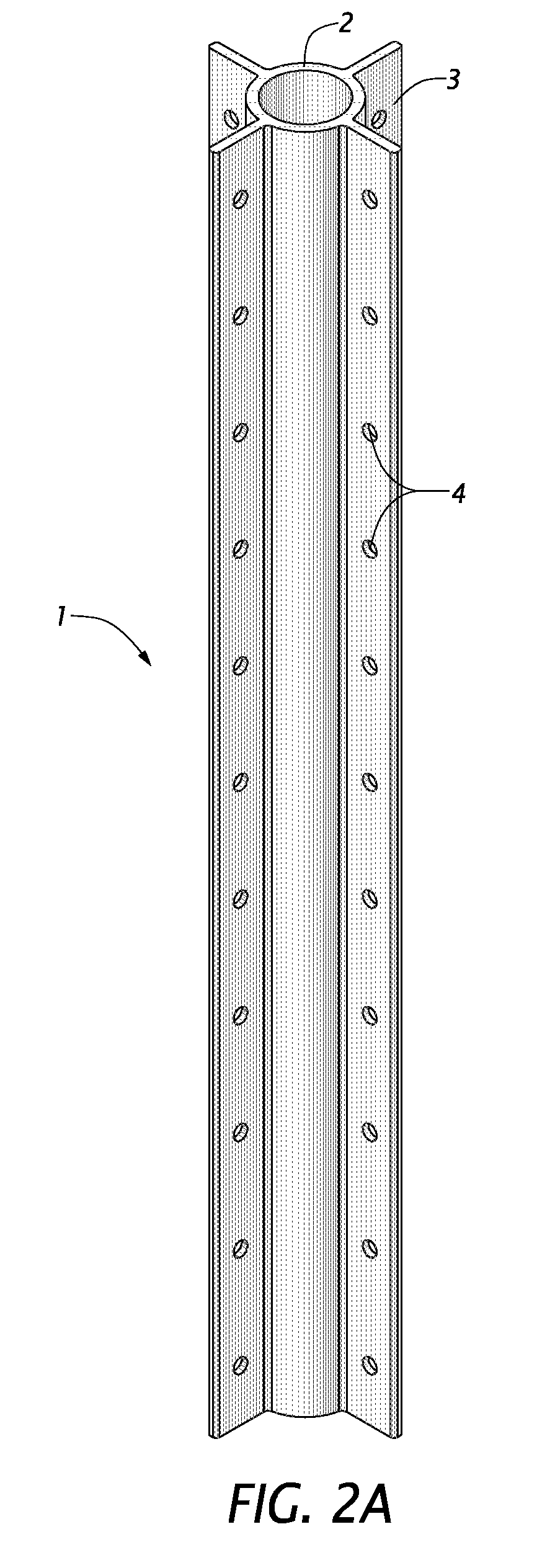
Moreover, since the size of the flanged tube structural member is relatively manageable, as are the other components of the structural netting systems described and claimed herein, they may be brought into and assembled within confined quarters or low-
accessibility locations where bringing in a larger component, a pre-assembled structure or partially assembled components would be impossible or highly difficult.

