Exposure apparatus and exposure method, and device manufacturing method

a technology of exposure apparatus and exposure method, which is applied in the direction of photomechanical apparatus, instruments, printers, etc., can solve the problems of difficult to ignore short-term variation of measurement values, measurement error at a level that cannot be ignored, and the requirement for position control accuracy of wafers has gradually become tighter

Active Publication Date: 2013-07-18
NIKON CORP
View PDF3 Cites 41 Cited by
  • Summary
  • Abstract
  • Description
  • Claims
  • Application Information

AI Technical Summary

Benefits of technology

[0011]According to a first aspect of the present invention, there is provided a first exposure apparatus which exposes an object by an energy beam via an optical system, the apparatus comprising: a moving member holding the object which is movable along a predetermined plane including a first axis and a second axis orthogonal to each other, and has a first grating provided at a position on an opposite side of the optical system with respect to a surface on which the object is mounted; a first measurement system which measures a first position information of the moving-member by irradiating a first measurement beam from below on the first grating and receiving light from the first grating of the first measurement beam, when the moving member moves in a first predetermined range within the predetermined plane;

Problems solved by technology

However, due to finer patterns accompanying higher integration of semiconductor devices in recent years, requirements for position control performance of a wafer stage with higher accuracy have increased, and as a consequence, it has become difficult to ignore short-term variation of measurement values caused by temperature change of the atmosphere on the beam path of a laser interferometer, and/or air fluctuation which occurs due to the influence of temperature gradient.
However, with more and more finer sem

Method used


Image

  • Exposure apparatus and exposure method, and device manufacturing method
  • Exposure apparatus and exposure method, and device manufacturing method
  • Exposure apparatus and exposure method, and device manufacturing method

Examples


first embodiment

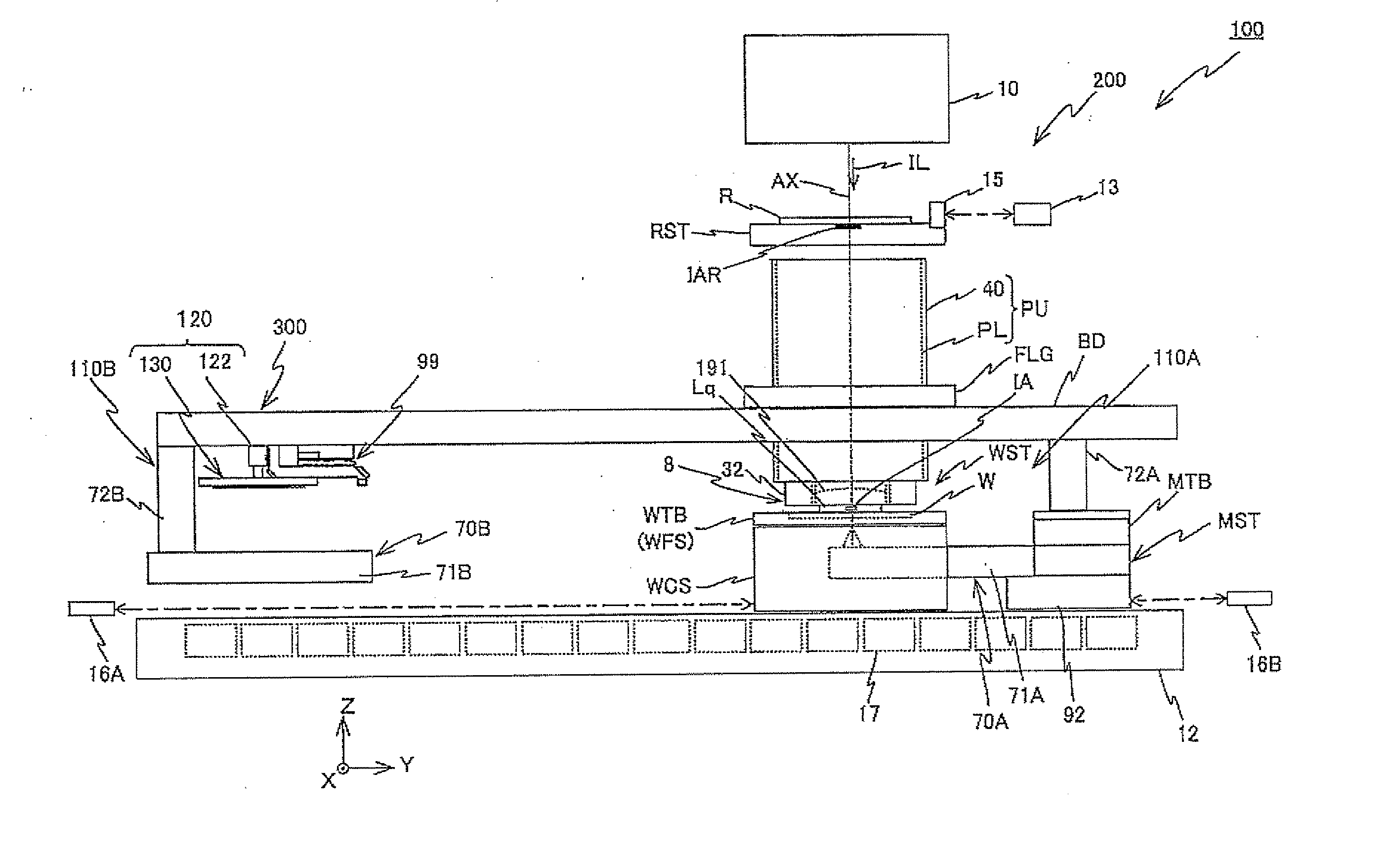
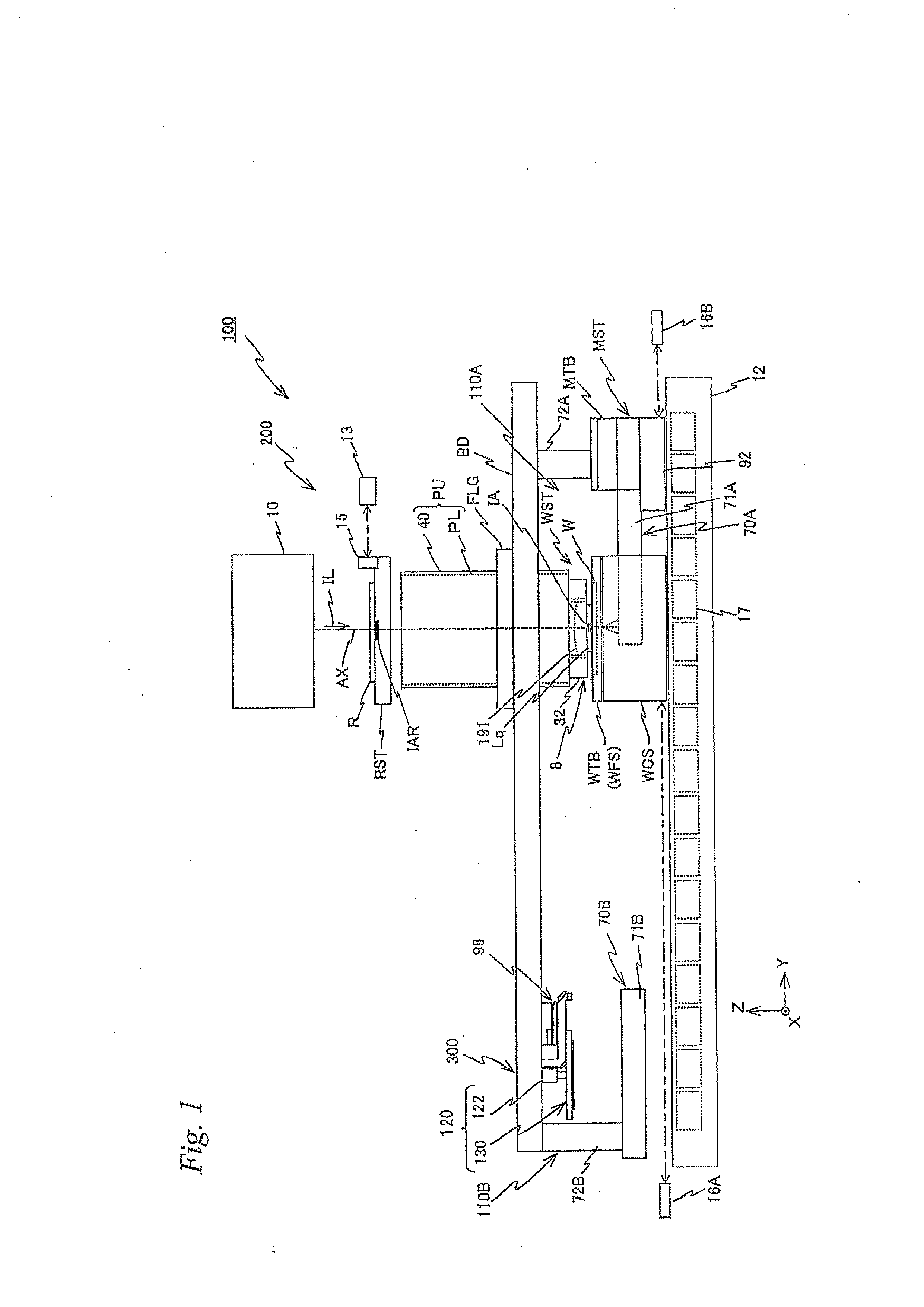
[0082]Hereinafter, a first embodiment will be described, referring to FIGS. 1 to 38E.

[0083]FIG. 1 schematically shows a structure of an exposure apparatus 100 related to the first embodiment. This exposure apparatus 100 is a projection exposure apparatus using a step-and-scan method, or a so-called scanner. As it will be described later on, in the present embodiment, a projection optical system PL is provided, and hereinafter, the description will be made with a direction parallel to an optical axis AX of this projection optical system PL referred to as a Z-axis direction (Z direction), a direction in which a reticle and a wafer are relatively scanned within a plane orthogonal to the Z-direction referred to as a Y-axis direction (Y direction), and a direction orthogonal to the Z-axis and the Y-axis referred to as an X-axis direction (X direction), and rotation (tilt) directions around the X-axis, the Y-axis, and the Z-axis referred to as θx, θy, and θz directions, respectively.

[0084...

second embodiment

[0427]Next, a second embodiment will be described, based on FIG. 39 to FIG. 55. Here, components which are the same or similar as in exposure apparatus 100 of the first embodiment previously described will have the same or similar reference signs, and the description thereabout will also be simplified or omitted.

[0428]FIG. 39 schematically shows a structure in a planar view of an exposure apparatus 1000 related to the second embodiment. Further, FIG. 40 shows a block diagram of an input / output relation of a main controller 20, which mainly structures a control system of exposure apparatus 1000 and has overall control over each section.

[0429]Exposure apparatus 1000 related to the second embodiment is equipped with two wafer stages WST1 and WST2, instead of wafer stage WST previously described, which are structured similarly to wafer stage WST. Further, in exposure apparatus 1000, components listed in (a) to (j) below differ from exposure apparatus 100 previously described.

(a) Instead...


PUM

PropertyMeasurementUnit
Angleaaaaaaaaaa
Angleaaaaaaaaaa
Timeaaaaaaaaaa

Abstract

An exposure apparatus is equipped with a table which holds a wafer and is movable along an XY plane and has a grating provided on its rear surface, an encoder which irradiates a first measurement beam on the grating from below, receives a return light, and measures a first position information of the table when the table moves in a predetermined range, and another encoder which has a head section provided in a frame and irradiates a second measurement beam on a different grating on the table from the head section, receives a return light, and can measure a second position information of the table, concurrently with measurement of the first position information by the encoder when the table moves in predetermined range. A controller drives the table, based on position information having a higher reliability of the first and the second position information.

Description

CROSS-REFERENCE TO RELATED APPLICATIONS[0001]This non-provisional application claims the benefit of Provisional Application No. 61 / 581,293 filed Dec. 29, 2011, and Provisional Application No. 61 / 581,360 filed Dec. 29, 2011, the disclosures of which are hereby incorporated herein by reference in its entirety.BACKGROUND OF THE INVENTION[0002]1. Field of the Invention[0003]The present invention relates to exposure apparatuses and exposure methods, and device manufacturing methods, and more particularly to an exposure apparatus and an exposure method used in a lithography process to manufacture electron devices (microdevices), and a device manufacturing method using the exposure apparatus and the exposure method.[0004]2. Description of the Background Art[0005]Conventionally, in a lithography process to manufacture electron devices (microdevices) such as a semiconductor device (an integrated circuit and the like), a liquid crystal display device and the like, a projection exposure appara...

Claims


Application Information

Patent Timeline
IPC IPC(8): G03F9/00G03F7/20
CPCG03F7/70725G03F7/70775Y10T29/49764G03F7/20G03F9/7049G03F7/709G03F9/7076G03F9/7088
Inventor SHIBAZAKI, YUICHI
Owner NIKON CORP
Why Eureka
Try Eureka