Image forming method

a technology of image forming and forming solution, which is applied in the direction of instruments, electrographic process equipment, optics, etc., can solve the problems of reducing affecting the image quality, and consuming more than half of the consumption power of toner heating, etc., to achieve a higher drying rate, reduce the supply amount of fixing solution, and improve the fixing rate

Inactive Publication Date: 2013-08-08
KONICA MINOLTA BUSINESS TECH INC
View PDF2 Cites 5 Cited by
  • Summary
  • Abstract
  • Description
  • Claims
  • Application Information

AI Technical Summary

Benefits of technology

[0036]According to the image forming method of the present invention, a fixing solution contains an ester compound (hereinafter referred to as a “specific ester compound”) represented by at least one of general formula (1) and general formula (2), and thus higher fixing rate and higher drying rate sire realized while the supply amount of fixing solution is reduced, and a wet feeling is reduced on a formed image and a nigh fixing strength is obtained.

Problems solved by technology

However, in the image forming device of the thermal fixing system described above, about more than half of consumption power is consumed to heat the toner.
However, there are a few problems in the wet fixing system.
For example, when in order for a high fixing strength to be obtained, a large amount of fixing solution is coated on an image support such as paper, a problem exists in which, the toner particles constituting a toner image are moved on the image support by the excessive amount of fixing solution to thereby degrade the image quality, and a problem exists in which drying time is elongated, which degrades the fixing responsiveness (see Patent Literature 1 and 2).
Furthermore, a problem exists in which a remarkable feeling of liquid left in paper (a wet feeling when paper is touched with hands) is produced.
Moreover, for example, when, as a fixing solution, an oil droplet water solution-type fixing solution is used in which an organic compound insoluble or poorly soluble in water is dispersed and mixed with water, if a large amount of fixing solution is supplied, an image support such as paper absorbs water in the fixing solution, and thus a crease or a curl is generated on the image support.
This causes a problem of reducing the stable and high-speed transport properties of the linage support which is required in the image forming device (see Patent Literature 3).
As to the fixing responsiveness, when the rate at which the fixing solution is softened for the toner is low, it is necessary to decrease the image processing rate of the image forming device, and thus there is a problem in which an image processing capacity that the image forming device originally has cannot be achieved.

Method used

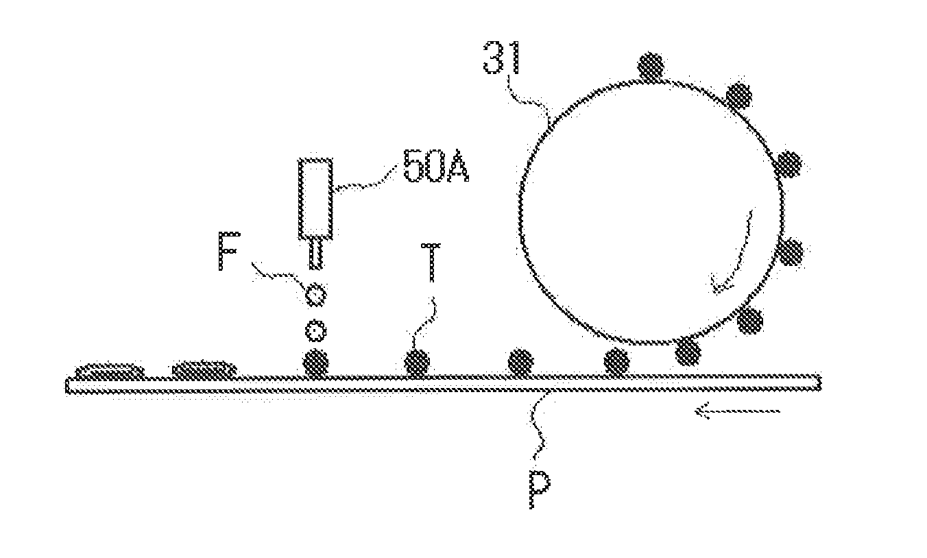
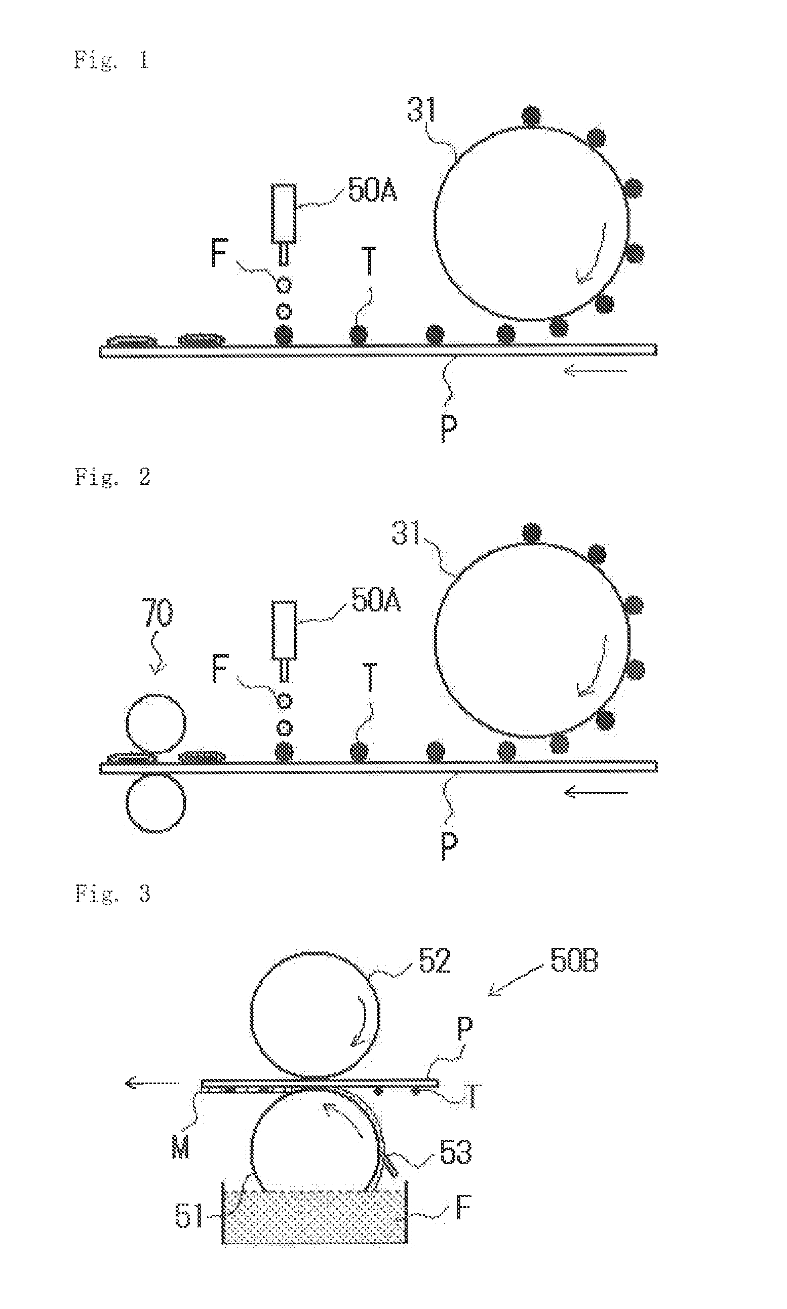
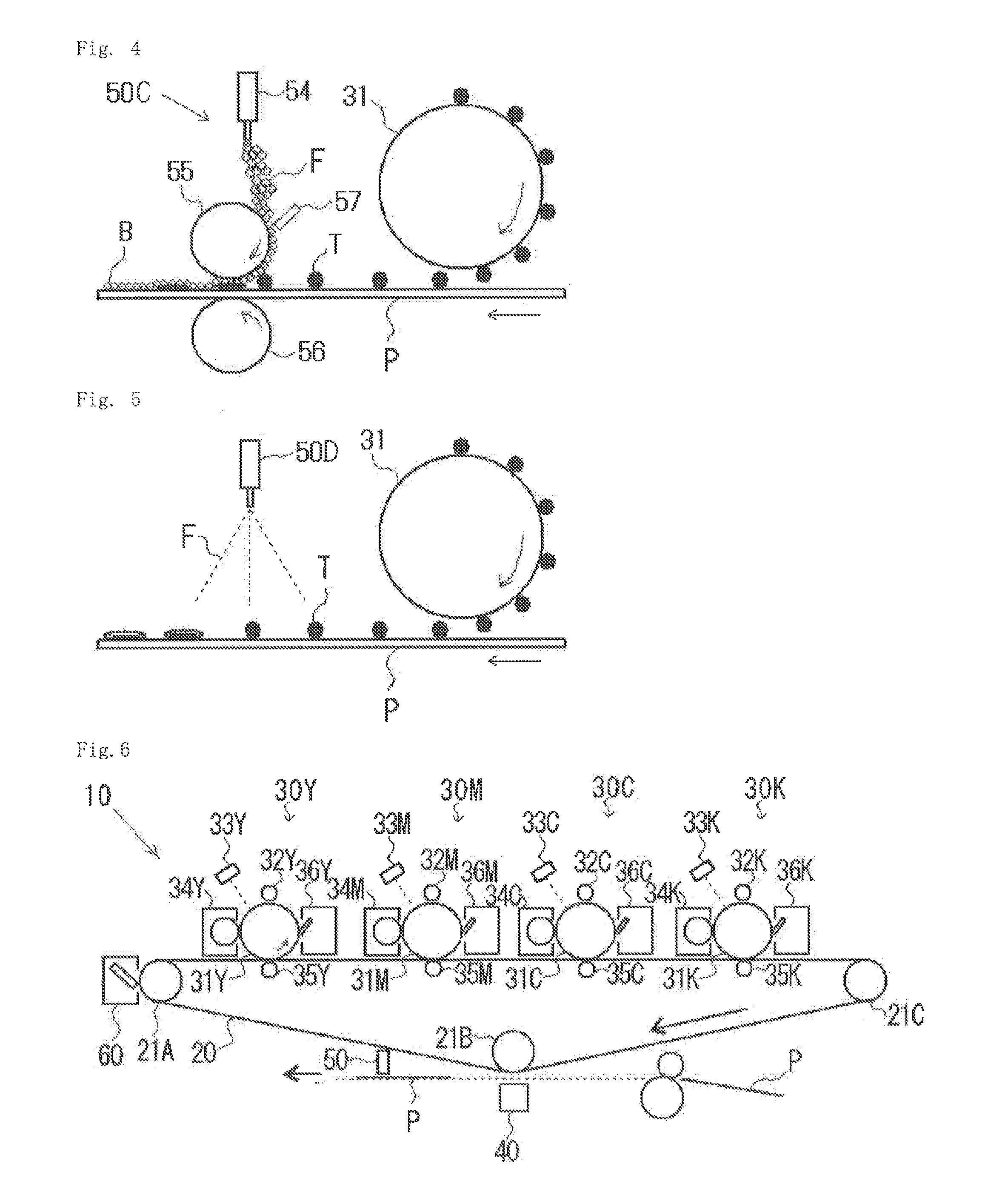

Image

  • Image forming method
  • Image forming method
  • Image forming method

Examples


production example 1

of the Toner

[0207](1) Preparation of a Binder Resin Particle Dispersion Solution

[0208]In a reaction container having an agitation device, a temperature sensor, a cooling tube and a nitrogen introduction device, 4 parts by mass of C10H21(OCH2CH2)2SO3Na anionic surfactant was put together with 3040 parts by mass of ion exchange water, and thus a surfactant aqueous solution was prepared. To the surfactant aqueous solution described above, a polymerization initiator solution obtained by dissolving 10 parts by mass of potassium persulfate in 400 parts by mass of ion exchange water was added, the temperature was increased to 75° C. and thereafter a monomer solution formed of 532 parts by mass of styrene, 200 parts by mass of n-butyl acrylate, 68 parts by mass of methacrylic acid and 16.4 parts by mass of n-octylmercaptan was dropped into the reaction container for 1 hour. After the dropping, the resultant substance was polymerized by being heated and agitated at 75° C. for 2 hours, and th...

production example 2

of the Toner

[0216]A toner [2] was produced in the same manner as in the Production example 1 of the toner except that the amount of methacrylic acid added in the preparation of the binder resin particle dispersion solution was changed to 120 parts by mass. The glass transition temperature of the binder resin particles produced was 42° C., and the weight-average molecular weight thereof was 30,000. In addition, the content of a dissociation acid monomer in the binder resin particles produced was 15%.

production example 3

of the Toner

[0217]In a flask having an agitation device, a nitrogen introduction tube, a temperature control device and a distillation column, the following polycarboxylic acid and polyhydric alcohol were poured, the temperature of this reaction solution was increased to 190° C. for 1 hour, and after it was confirmed that the reaction system was uniformly agitated, a catalyst Ti(OBu)4 (0.003 mass % to the total amount of carboxylic acid component of the polyester resin) was put in.[0218](Polycarboxylic Acid)[0219]terephthalic acid: 30 parts by mass[0220]isophthalic acid: 3 parts by mass[0221]adipic acid: 3 parts by mass[0222](Polyhydric alcohol)[0223]2-mol adduct of 2,2-bis(4-hydroxyphenyl) propanepropylene oxide: 75 parts by mass[0224]2-mol adduct of 2,2-bis(4-hydroxyphenyl) propaneethylene oxide adduct: 25 parts by mass

[0225]Furthermore, while the generated water was being distilled away, the temperature was increased to 240° C. for 6 hours, the dehydration condensation reaction w...


PUM


Abstract

In an image forming method of wet fixing system, the fixing solution contains an ester compound represented by at least one of general formula (1) and general formula (2) below:
R11—(CO)—O—R12  General formula (1):
where R11 represents a linear or branched alkyl group having at least one hydroxyl group and 2 to 11 carbon atoms, and R12 represents a linear or branched alkyl group having 1 to 4 carbon atoms;
R21—O—(CO)—R22—(CO)—O—R23  General formula (2):
where R21 represents a linear or branched aliphatic hydrocarbon group having 1 to 4 carbon atoms, R22 represents a linear or branched aliphatic hydrocarbon group having at least one hydroxyl group and 1 to 8 carbon atoms, and R23 represents a linear or branched aliphatic hydrocarbon group having 1 to 4 carbon atoms.

Description

BACKGROUND Of THE INVENTION[0001]1. Field of the Invention[0002]The present invention relates to an image forming method of a wet fixing system using an electrophotographic system.[0003]2. Description of the Related Art[0004]An image forming device such as a printer, a facsimile machine or a copying machine is a device that forms an image including characters and symbols on an image support such as paper, cloth or an OHP sheet based on image information.[0005]In particular, the linage forming devices of an electrophotographic system are widely utilized in, for example, offices because it is possible to form a nigh minute image on a plain paper at high speed. In the image forming device of the electrophotographic system described above, there is widely used a thermal fixing system in which the toner constituting a toner image on an image support is heated and melted, the molten toner is pressurized, and thus the toner image is fixed on the image support. With this thermal fixing syst...

Claims


Application Information

Patent Timeline
Patent Type & Authority Applications(United States)
IPC IPC(8): G03G15/20
CPCG03G15/0189G03G15/2096G03G13/20G03G2215/2074G03G11/00
Inventor FUJISAKI, NATSUKOOBATA, HIROAKISHIBATA, KOJIHORI, ANJUTAMURA, KISHIO
Owner KONICA MINOLTA BUSINESS TECH INC
Why Eureka
Try Eureka