While deployment of optical
fiber to an edge of the core data network would be advantageous from a
network performance perspective, it is often impractical to connect all
high bandwidth data networking points with optical
fiber at all times. Instead, connections to remote edge access networks from core networks are often achieved with wireless radio, wireless
infrared, and / or
copper wireline technologies.
However, cellular base stations or WLAN access points inevitably become very high data bandwidth demand points that require continuous
connectivity to an optical
fiber core network.
These backhaul requirements cannot be practically satisfied at ranges of 300 m or more by existing
copper wireline technologies.
Even if LAN technologies such as
Ethernet over multiple dedicated
twisted pair wiring or
hybrid fiber / coax technologies such as cable modems are considered, it is impractical to backhaul at such data rates at these ranges (or at least without adding intermediate
repeater equipment).
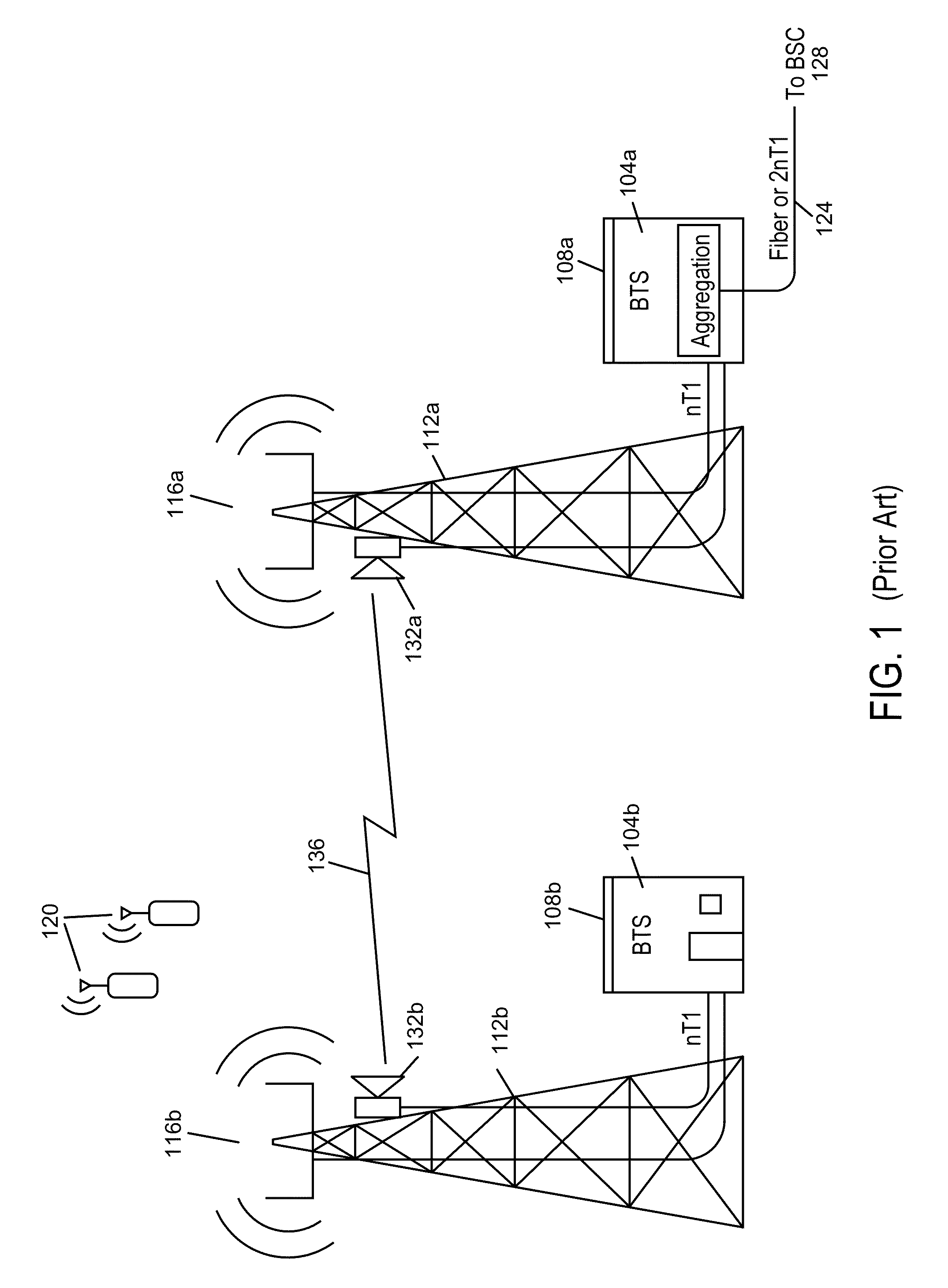
Such alignment is almost impossible to maintain over extended periods of time unless the two radios have a clear unobstructed
line of sight (LOS) between them over the entire range of separation.
Furthermore, such precise alignment makes it impractical for any one such
microwave backhaul radio to communicate effectively with multiple other radios simultaneously (i.e., a “point to multipoint” (PMP) configuration).
Although impressive
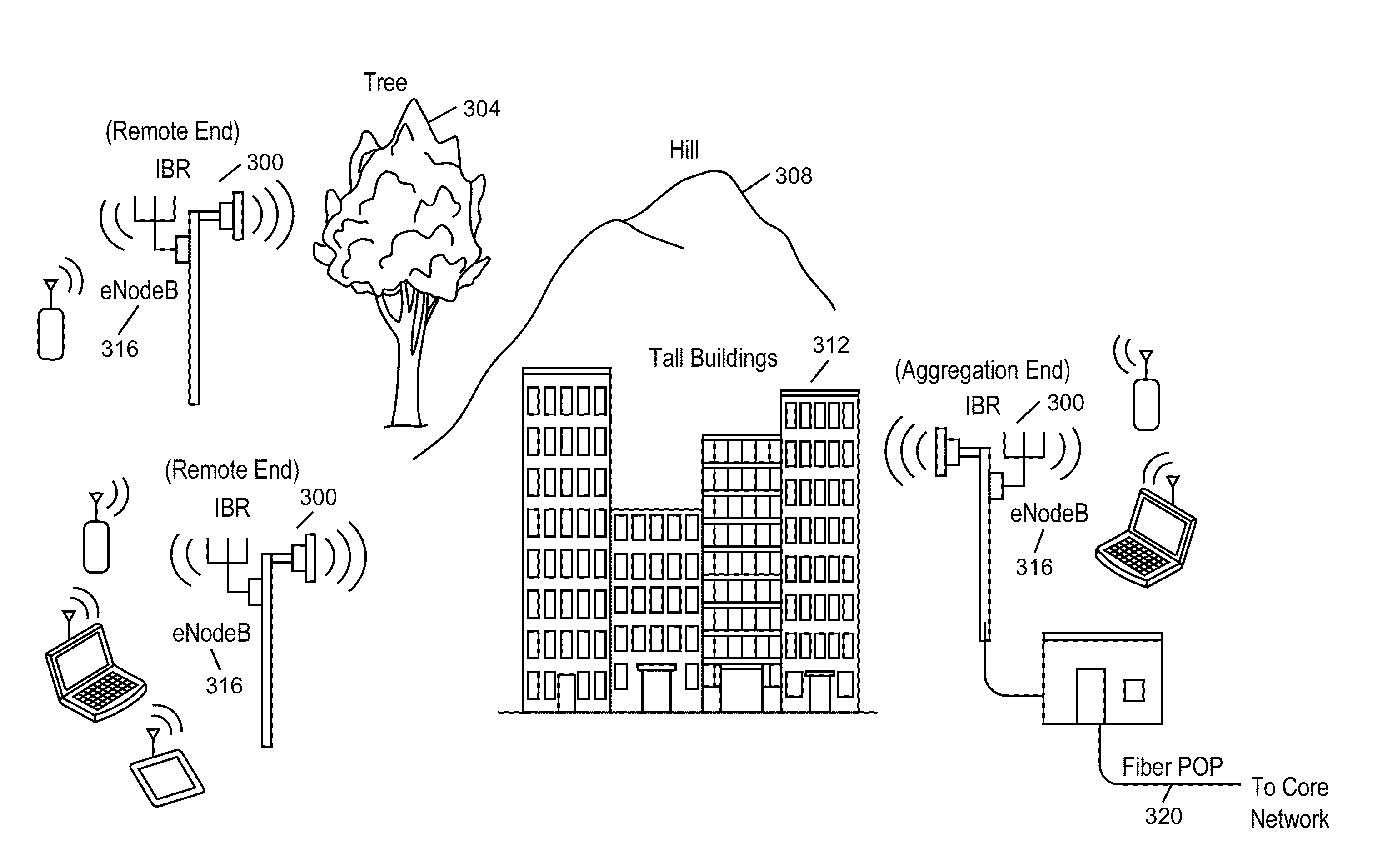
performance results have been achieved for edge access, such results are generally inadequate for emerging backhaul requirements of data rates of 100 Mb / s or higher, ranges of 300 m or longer in obstructed LOS conditions, and latencies of 5 ms or less.
In particular, “street level” deployment of cellular base stations, WLAN access points or LAN gateways (e.g., deployment at street lamps, traffic lights, sides or rooftops of single or low-multiple story buildings) suffers from problems because there are significant obstructions for LOS in urban environments (e.g., tall buildings, or any environments where tall trees or uneven
topography are present).
Because of their very narrow
antenna radiation patterns and manual alignment requirements, these conventional
microwave backhaul radios are completely unsuitable for applications with remote data network backhaul in obstructed LOS conditions, such as deployment on street lamps, traffic lights, low building sides or rooftops, or any fixture where trees, buildings, hills, etc., which substantially impede
radio propagation from one point to another.
Additionally, such conventional microwave backhaul radios typically have little or no mechanism for avoiding unwanted interference from other radio devices at the same channel frequency (other than the narrowness of their
radiation patterns).
Thus, users of such equipment are often skeptical of deployment of such conventional backhaul radios for critical applications in unlicensed spectrum bands.
This is slow, inefficient, and error prone as well as wasteful of spectrum resources due to underutilization, even with the undesirable restriction of unobstructed LOS conditions.
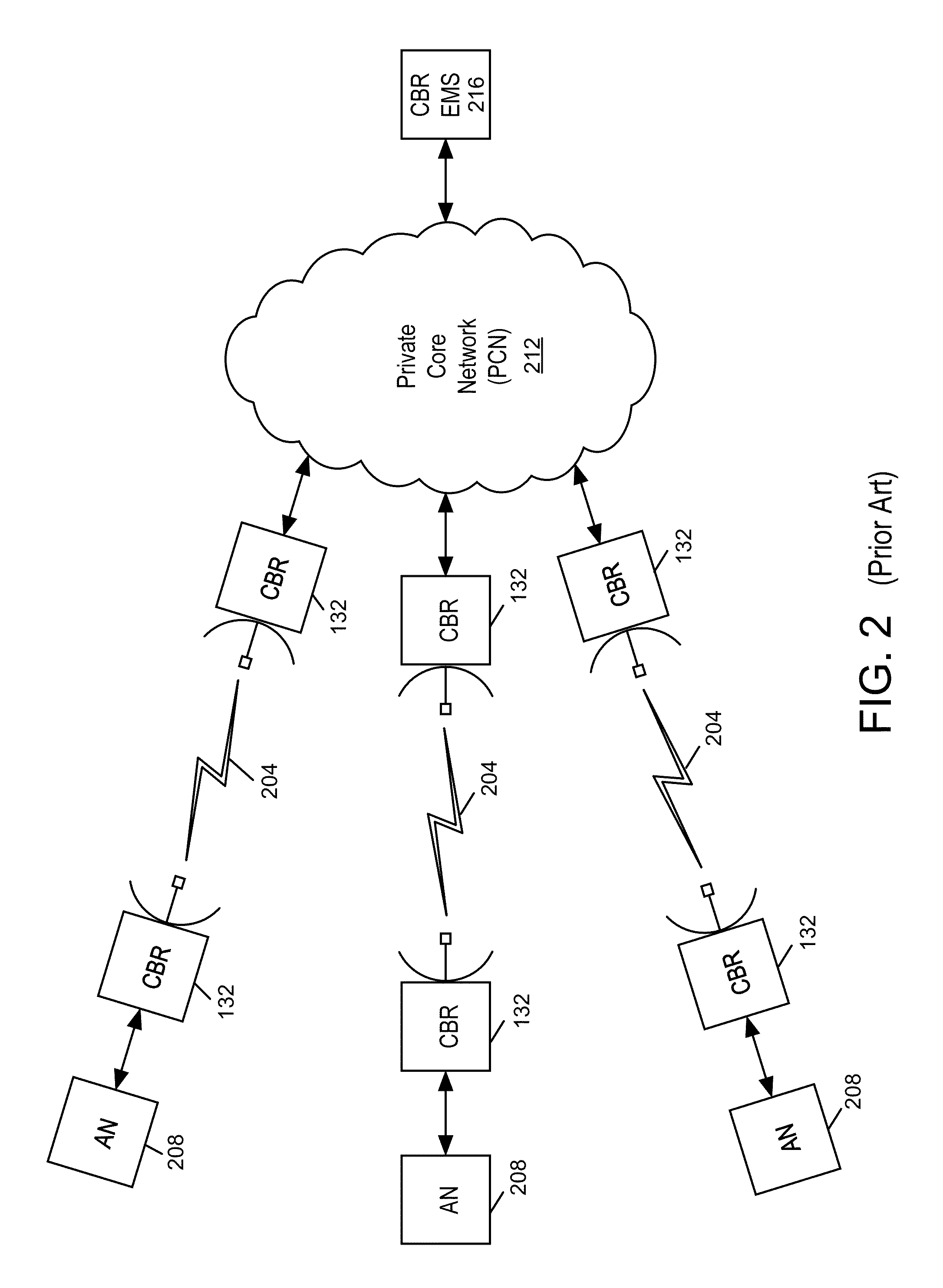
Furthermore, once deployed in the field, conventional microwave backhaul radios are typically islands of
connectivity with little or no capability to monitor the spectrum usage broadly at the deployment location or coordinate with other radios in the vicinity to optimally use spectrum resources.
However, such a conventional EMS 216 does not dynamically modify operational policies or configurations at each CBR 132 in response to mutual interactions, changing network loads, or changes in the
radio spectrum environment in the vicinity of the deployed CBRs 132.
As a result of the foregoing deficiencies with conventional backhaul radios and conventional approaches to obstructed
line of sight systems, there exists no practical approach to the deployment, monitoring and operation of obstructed non-
line of sight systems in the presence of unlicensed or licensed conventional backhaul radios or other licensed services according to 47 Code of Federal Regulations (C.F.R.) §101 within the same operational bands.
Further, such deficiencies prevent the rapid deployment of new backhaul radios configured for co-channel operation with these systems, including conventional backhaul
radio networks and other 47 C.F.R. §101 systems.

