Valve device and failure detector of hydraulic circuit

a technology of failure detector and valve device, which is applied in the direction of valve operating means/releasing devices, service pipe systems, transportation and packaging, etc., can solve the problems of large external dimensions and weight, complex structure of valve devices, and increased component costs, so as to prevent misjudgment of failures, reduce device cost, and simple structure

Active Publication Date: 2013-09-12
HONDA MOTOR CO LTD
View PDF15 Cites 3 Cited by
  • Summary
  • Abstract
  • Description
  • Claims
  • Application Information

AI Technical Summary

Benefits of technology

[0021]The failure detector of the hydraulic circuit according to this invention determines that the driving sources of the valve device are normal and either of the first or second hydraulic circuit has a failure in the case where only one of either a value based upon pressure detected by the first pressure detection section or a value based upon pressure detected by the second pressure detection section falls out of a normal range. Thus, when a failure occurs to the hydraulic circuit, it can be determined whether its cause is a failure of the driving sources of the valve device or a failure of the first and second hydraulic circuits and which of the first or second hydraulic circuit has the failure when the failure has occurred to either of the first or second hydraulic circuit (120-1, 120-2). Therefore, since the cause of the failure can be identified quickly and precisely, an appropriate fail safe action can be taken. Further, the failure detector can identify the cause of the failure in the hydraulic circuit by using the values based upon pressure detected by the first and second pressure detection sections, which can streamline control specifications of the failure detector and contribute to reduction in cost of the device.
[0022]Also, in the failure detector, the failure detection section (150) may determine that values based upon pressure detected by the first or second pressure detection section (122-1, 122-2) have fallen out of a normal range in the case where differences (PxA, PxB) between the detected values of pressure detected by the first and second pressure detection sections (122-1, 122-2) and a predetermined pressure command exceed a predetermined range and their durations (TxA, TxB) last longer than a predetermined duration (Tx0). This enables to perform failure determination of the driving sources of the valve device or the first and second hydraulic circuits more accurately so as to prevent misjudgment of failures in the hydraulic circuit. It is noted that the above characters in parentheses represent, by way of example, reference characters of components of embodiments to be described herein later.
[0023]The valve device according to the present invention has a distinctly simple structure and is capable of major reduction in size, weight and cost compared to a conventional valve device. The valve device can improve accuracy of hydraulic control by allowing to perform opening and closing of plural oil passages at an identical timing.
[0024]The failure detector according to the present invention can swiftly determine the kind of failure in the hydraulic circuit including the plural valve mechanisms that switch opening and closing of the plural oil passages.

Problems solved by technology

There has been a problem with the valve device comprising the actuator consisting of the solenoid that the valve device has a complicated structure with a large number of components and large external dimensions and weight due to various built-in materials such as metal solenoid and magnet.
Also, there is a problem that component costs increase.
In an automatic transmission for a vehicle, in particular, plural pieces (normally around 4-6 pieces) of the valve devices having the said structure are used for one automatic transmission for the vehicle, and hence the problem of large weight and component costs becomes all the more serious.
Furthermore, there is a problem with the valve device having the said structure that operating noise when opening and closing the oil passage grows due to driving noise of the solenoid.
In addition, hydraulic control using a hydraulic circuit comprising the valve device has the following problem.
However, the actuator structure provided by each valve device does not have completely identical physical dimensions and configuration with each other.
Thus, there is a problem that a certain time-lag occurs because the timing of opening and closing of each oil passage by means of each valve device is not completely the same even if switching voltage application to each valve device simultaneously.
This might interfere with improving accuracy of hydraulic pressure control using the oil hydraulic circuit.
Moreover, when a failure such as circulating malfunction of hydraulic fluid occurs to the hydraulic circuit comprising the valve device, it is needed to quickly identify its cause and take an appropriate fail safe action.
However, failures of the hydraulic circuit provided with the valve device include circulating failures of the hydraulic fluid caused by metal abrasion powder (i.e., contamination) contained in the hydraulic fluid inside the hydraulic circuit (i.e., the oil passage) and electrical failures such as malfunction or energization failures of a solenoidal coil of the valve device.
Therefore, a conventional control device for determining a failure of the hydraulic circuit has complicated control specifications which require time to determine the kind of the failure.

Method used


Image

  • Valve device and failure detector of hydraulic circuit
  • Valve device and failure detector of hydraulic circuit
  • Valve device and failure detector of hydraulic circuit

Examples


first embodiment

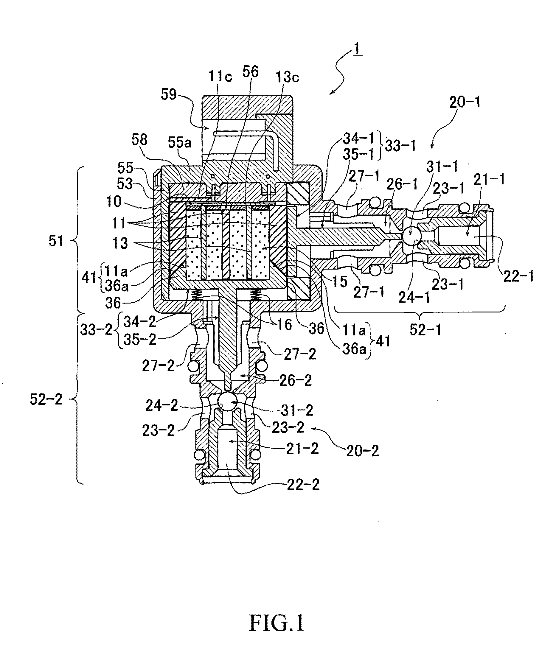
[0036]FIG. 1 is a sectional side view showing a valve device 1 according to a first embodiment of the present invention. The valve device 1 shown in the figure is a valve device which is suitable for use in controlling flow of hydraulic fluid for gearshift control in an automatic transmission installed in a vehicle. This valve device 1 comprises a set of a first valve mechanism 20-1 and a second valve mechanism 20-2 and a single contraction-type PCV gel actuator (i.e., a high polymer gel actuator) 10 that drives ball valves (i.e., valve plugs) 31-1, 31-2 of the set of the valve mechanisms 20-1, 20-2. The valve device 1 is configured to simultaneously drive the set of the valve mechanisms 20-1, 20-2 by operation of the contraction-type PVC gel actuator 10 so as to simultaneously open and close two different oil passages 21-1, 21-2.

[0037]The valve device 1 includes a roughly cubical body part (i.e., a valve body) 51 housing the PVC gel actuator 10, a first roughly cylindrical shank 52...

second embodiment

[0076]Next, a second embodiment of the present invention will be described. In the description of the second embodiment and the corresponding figures, like reference characters refer to components corresponding or equivalent to those of the first embodiment and a detailed description thereof is dispensed with. The other features than those described as below are the same as in the first embodiment. The same holds for the other embodiments of the invention.

[0077]FIGS. 6A and 6B are diagrams illustrating a valve device 1-2 of the second embodiment. FIG. 6A is a diagram illustrating a state when not applying voltage to a PVC gel actuator 10, and FIG. 6B is a diagram illustrating a state when applying voltage sides of the inclined planes 11b, 36b. The guide mechanism 17 installs the negative plate 11 and the plunger 33-2 to be inseparable with each other by engaging the roughly wedge-shaped protruding part of the projection 11b and the wedge-shaped protruding part of the projection 36b ...


PUM


Abstract

A valve device is provided with a contraction-type high polymer gel actuator which laminates slab-like negative plates and mesh-like positive plates alternately and interleaves high polymer gel between each negative plate and each positive plate, and with a first and a second valve mechanisms driven by the gel actuator. The direction of deformation of expansion and contraction of the high polymer gel actuator is the same as the driving direction of the first valve mechanism and perpendicular to the driving direction of the second valve mechanism. The valve device is composed in such a way as to switch opening and closing of a first fluid passage and a second fluid passage simultaneously by means of deformation of expansion and contraction by controlling voltage applied to the high polymer gel actuator. This allows to compose a valve device that can open and close plural oil passages at an identical timing.

Description

CROSS-REFERENCE TO RELATED APPLICATION[0001]The present disclosure relates to subject matter contained in Japanese Patent Application No. 2012-051055, filed on Mar. 7, 2012, the disclosure of which is expressly incorporated herein by reference in its entirety.BACKGROUND OF THE INVENTION[0002]1. Technical Field[0003]This invention relates to a valve device which is suitable for use in hydraulic control of a hydraulic apparatus such as an automatic transmission installed in a vehicle, and a failure detector for a hydraulic circuit comprising the valve device.[0004]2. Description of the Related Art[0005]Conventionally, as a valve device for switching flow passages of hydraulic fluid for gearshift control in an automatic transmission installed in a vehicle, a valve device comprising an actuator consisting of a solenoid is used. As shown, for example, in Japanese Patent Application Publication No. 2003-74729 (Patent Document 1), this type of valve device comprises a valve plug for openin...

Claims


Application Information

Patent Timeline
Patent Type & Authority Applications(United States)
IPC IPC(8): F16K31/02F16K37/00F16H61/12
CPCF16H61/0251F16H61/12F16H2061/0253F16K31/02F16K37/0083F16K11/18Y10T137/87161Y10T137/8158Y10T137/8741Y10T137/87217Y10T137/87233
Inventor YAJIMA, NAOKITOMARI, TATSUHIROUENO, MINORU
Owner HONDA MOTOR CO LTD
Why Eureka
Try Eureka