Pump having a pressure compensated annular volume

a technology of annular volume and pump, which is applied in the field of pumps, can solve the problems of limited ability of each individual pump stage in itself to deliver pressure increase, long existing construction, and short service life of the entire pump, so as to reduce the wear resulting from any sand production and facilitate the operation of the pump

Active Publication Date: 2013-09-12
NORALI
View PDF5 Cites 16 Cited by
  • Summary
  • Abstract
  • Description
  • Claims
  • Application Information

AI Technical Summary

Benefits of technology

[0015]Gas lift is widely used as artificial lift on installations at sea where there is access to produced gas from the separator unit located on the installation. The principle is based on re-injecting produced gas into the annulus, or more specifically the production annulus, between the production tubing and the casing and down towards the production packer in the bottom of the well. Gas lift valves are placed at different levels in the tubing. These are one-way valves which permit the gas in the annulus to flow into the tubing, thereby reducing the pressure of the hydrostatic column inside the tubing. This occurs because the gas has a lower density than the fluids inside the tubing, thereby causing the hydrostatic counter-pressure on the reservoir to also be reduced, with the result that, by means of the injected gas, the reservoir pressure itself can force the produced fluids to the surface. In principle gas lift is an efficient system, but it requires investment in separate gas compressors, surface flow lines, Annulus Safety Valves (ASV), gas lift valves (GLV) and gas-tight pipe threads in the casing. The system can be difficult to operate in an optimal manner since the rate of mixture between oil, water and any gas produced from the reservoir will vary with shorter or longer intervals of time. In addition there is the problem that re-injected gas in the production annulus may leak out into the outer annuli through the casings. In order to reduce the risk of uncontrolled discharge of gas in the event of a system failure, several oil companies now want to develop an ISO VO version of the gas lift valves so that they can remove ASV, since it has been shown that these ASV's are subject to leakages. This change will help to increase the investment costs for the gas lift system.
[0029]The fact that the pump is divided into pump sections permits it to be installed in a well by means of cable operations, even though the pump is intended to be employed for permanent artificial lift, indicating that in most cases there will be a need for several pump sections in order to achieve sufficient pressure and production rate. This embodiment is not possible with today's ESP systems. In an embodiment the pump may be installed in the well by means of pipes. The fact that the installation can be undertaken by using industrial standard cable operations, coiled tubing, pressure pipes or drill pipes entails a substantial reduction in the installation costs compared to today's pumps which have to be installed as an integrated part of the production tubing. In addition, this reduces the costs of pulling the pump out again in the event of operational problems. Since the pump can be handled by cable in a wireline operation, it can also be employed during well interventions where wells need to have help to start production. During such temporary installations the pump will be pulled out of the well as soon as the well flows naturally due to the overpressure in the reservoir. This will be a far cheaper method than the present day method of injecting gas into the well by means of coiled tubing in order to start up the well.

Problems solved by technology

The reason for using several pump stages is that each individual pump stage in itself has limited ability to deliver pressure increase.
However, there are disadvantages with the technical design of existing multistage pumps, such as, for example, that all the pump stages are driven by one motor via a common shaft, with the result that the whole pump stops if the motor stops.
In addition, the existing constructions become very long due to the fact that the motor is mounted below the pump stages in the longitudinal direction.
This is a problem when the pump is employed in wells where the well path is deviated relative to the vertical.
In addition the bearings in today's pumps suffer from a short working life on account of severe loads and wear on impellers due to cavitation.
With this system the challenges are a relatively large drive gear which is located above and near the wellhead, friction between pump rod and pipe wall in the well, production of sand from the reservoir and a system efficiency of 0.4.
There are also restrictions as to how deep this type of pump system can be located based on material / strength limitations on the pump rod.
The systems have limited lifting capacity, and are therefore employed at lower production rates.
The system's design per se, together with operating conditions such as sand production, leads to regular operational stoppages.
In addition to increasing the direct operating costs, this leads to costs in connection with production delays.
This means that if the pump fails, the whole tubing has to be pulled out of the well.
This creates wear on electric cables and connectors and may also lead to earthing problems.
Normally it is electric motors of the induction motor type which drive the actual pump, and on account of the need for a great deal of power in the case of high rates and deep wells, these motors become relatively long.
In these motors there is little clearance between stator and rotor, with the result that small curvatures (deviations) in the well path can create contact between rotor and stator, leading to breakage.
Apart from the said mechanical problems, ESP systems have problems with handling the production of large amounts of sand and other solid particles such as scale.
Both of these factors cause wear on the impellers.
Free gas is also a problem for the actual electric motor since the gas has less ability than liquids to transport the heat generated by the electric motor.
All of these factors result in an estimated average life for an ESP system of around 1.5 years, but there are examples of these failing after only a few weeks in operation.
The costs of replacing an ESP will vary with the depth of the well, due to the fact that the whole production tubing has to be pulled out.
In addition to the direct costs of the operation, which involve the use of a drilling rig, the costs of production delays are also incurred.
One of the major weaknesses of today's ESP pumps is that all parts of the pump are integrated.
This means that if a breakage occurs on one or more of the components in the pump, the whole pump stops.
The system can be difficult to operate in an optimal manner since the rate of mixture between oil, water and any gas produced from the reservoir will vary with shorter or longer intervals of time.
In addition there is the problem that re-injected gas in the production annulus may leak out into the outer annuli through the casings.
With a frequency of between 30 and 60 strokes per minute, there is substantial wear on the contacts which have to reverse the electrical current, and considerable heat generation every time the piston has to change direction.
So far no one has managed to make linear motors which are practical and commercial, because, amongst other things, there is a huge increase in power consumption every time the motor has to change direction.

Method used


Image

  • Pump having a pressure compensated annular volume
  • Pump having a pressure compensated annular volume
  • Pump having a pressure compensated annular volume

Examples


Embodiment Construction

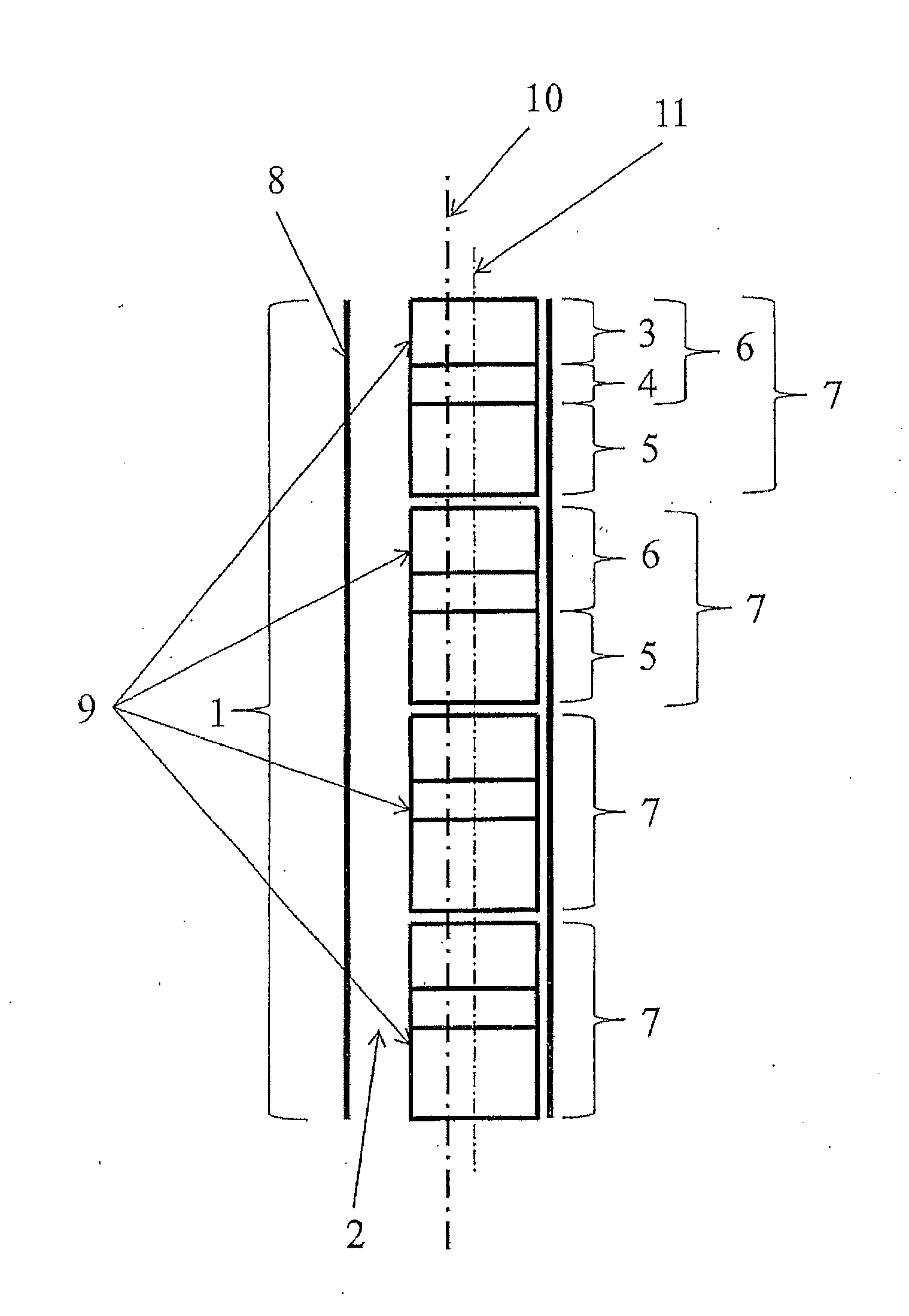
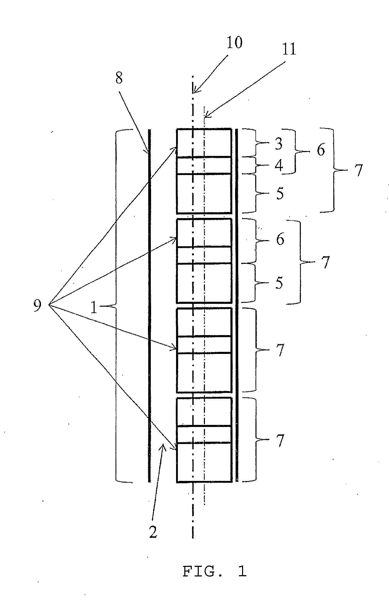
[0046]FIG. 1 illustrates a principle drawing of a pump section 1 where the pump steps 7 with inner casings 9 and a centre line 11 are located radially displaced, asymmetrical relative to a centre line 10 of the pump section 1. An annular volume 2 is thereby formed between the outer casing 8 in the pump section 1 and the inner casings 9 in the pump steps 7. The asymmetry is illustrated by the centre line 10 of the pump section 1 being displaced to the left of the common centre line 11 of the pump steps 7. FIG. 1 also shows that the four pump steps 7 each consist of a motor 5 and pump stage 6. It can also be seen in the figure that it is precisely in this embodiment illustrated here that each pump step 7 only has one pump stage 6. A pump stage 6 consists of an impeller 4 and a diffuser 3. The well fluid which has to be lifted to the surface will flow internally in each pump step 7.

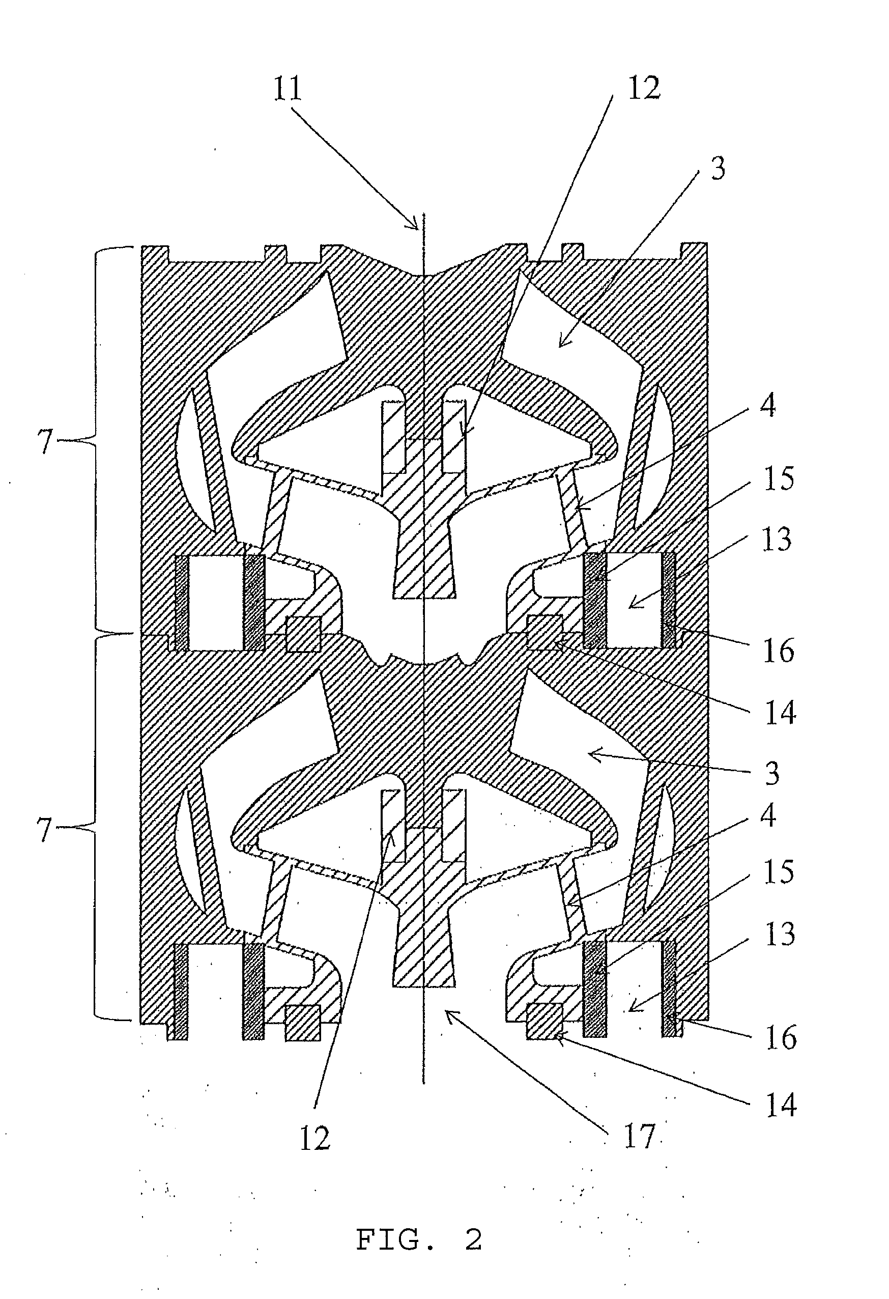
[0047]FIG. 2 illustrates an embodiment of two pump steps 7, both of which in this embodiment contain a pu...


PUM


Abstract

A pump and pump section, where the pump section has a centre line and where the pump section comprises at least one pump step,the pump step has a centre line and each pump step comprises a motor and one or more pump stages, and wherethe pump comprises an outer casing enclosing one or more inner casings,the outer casing forms an enclosure round the pump section and has a larger diameter then the inner casings, andthe inner casings form an enclosure round the at least one pump step,and where the centre line of the pump section is displaced relative to the centre line of the pump steps, thereby forming an annulus between the outer casing and the inner casing.

Description

CROSS-REFERENCE TO RELATED APPLICATIONS[0001]This application claims priority to Norwegian Patent Application No. 20120289, filed on Mar. 12, 2012, and entitled “PUMP HAVING A PRESSURE COMPENSATED ANNULAR VOLUME.” This priority application is incorporated herein by reference in its entirety.SCOPE OF THE PRESENT DISCLOSURE[0002]The present disclosure relates to a pump which is divided into separate sections, pump steps and pump stages. The pump may be installed down in wells in order to pump hydrocarbons and water to the surface.BACKGROUND OF THE PRESENT DISCLOSURE[0003]Centrifugal pumps are previously known for use down in oil-producing wells. These pumps employ a so-called multistage principle, where the pump consists of several vertically-arranged stages. A stage comprises substantially of an impeller and a diffuser. All the impellers are attached to a common shaft which passes through all the pump stages, and all of these stages are located inside one and the same casing. The sha...

Claims


Application Information

Patent Timeline
Patent Type & Authority Applications(United States)
IPC IPC(8): F01D25/24
CPCF04D1/063F01D25/24F04D29/628F04D13/10F01D1/00F04D13/12E21B43/128F04D13/086F04D29/426F04B47/06
Inventor ANDERSEN, GUNNAR
Owner NORALI
Why Eureka
Try Eureka