In-place resynthesis and remapping techniques for soft error mitigation in FPGA

a technology of remapping and resynthesis, applied in the field of fpga resynthesis and remapping, can solve the problems of high overhead in relation to cost, area and/or power, and the cost of more vulnerability to a single event upset (seu), and achieve the effect of reducing the cost of fpga techniques, and reducing the cost of fpga

Inactive Publication Date: 2013-11-14
RGT UNIV OF CALIFORNIA
View PDF29 Cites 52 Cited by
  • Summary
  • Abstract
  • Description
  • Claims
  • Application Information

AI Technical Summary

Benefits of technology

[0038]A self-evolutionary FPGA-based system can be built using IPR, IPF, and/or IPV running on a computer to pass a new-configuration to the FPGA-based system. Simple software or control logic can be added to measure the system in terms of the optimization objective, and to decide whether the new-configuration is accepted without re-doing any placement or routing of the FPGA. This type of self-evolution can be more accurate and more efficient compared to purely software-based resynthesis.
[0039]To measure fault tolerance, fault injection can ...

Problems solved by technology

Modern FPGAs use ever advancing fabrication technologies to achieve higher density at reduced power consumption levels, but at the cost of more vulnerability to a single event upset (SEU), such as caused by supply voltage fluctuations, electromagnetic coupling and environmental radiation.
Although this is not a critical concern for FPGAs used in prototypes, it is an issue that must be addressed when FPGAs are utilized in various system implementations, such as within inter...

Method used


Image

  • In-place resynthesis and remapping techniques for soft error mitigation in FPGA
  • In-place resynthesis and remapping techniques for soft error mitigation in FPGA
  • In-place resynthesis and remapping techniques for soft error mitigation in FPGA

Examples


embodiment 50

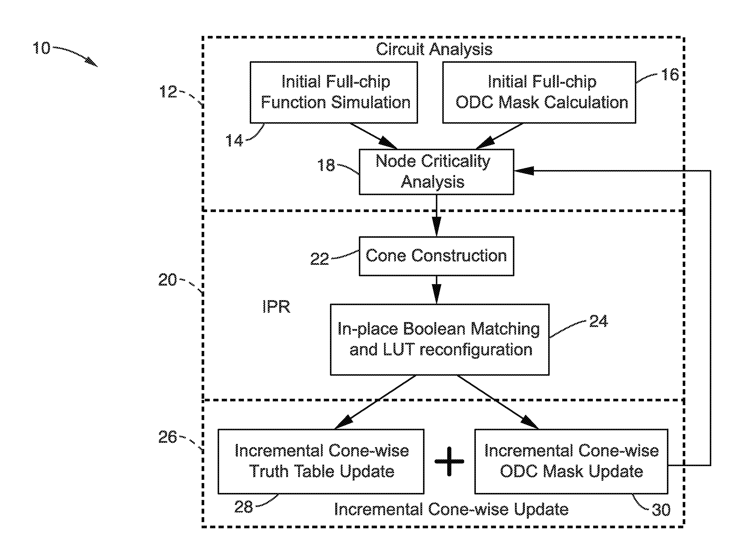
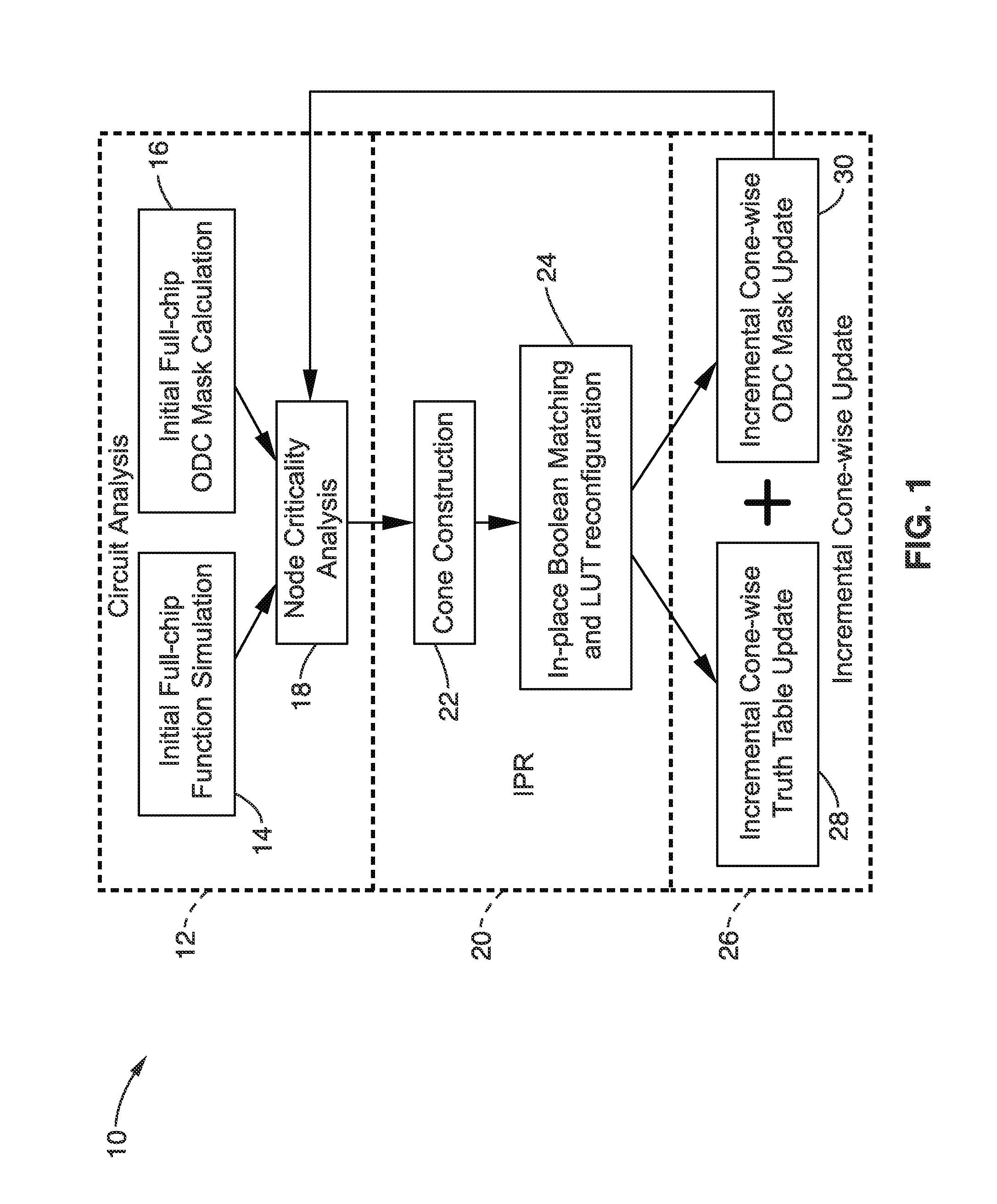
[0087]FIG. 4 illustrates an example architecture embodiment 50 of an FPGA-based emulator which provides efficient fault analysis. The emulator can be utilized during the circuit analysis (block 18 in FIG. 1) for efficient criticality computation and / or for full-chip evaluation. In addition, the emulator can be interfaced to a computer aided design (CAD) tool for interacting with the inventive in-place reconfiguration to provide information with increased accuracy, such as power estimation, fault injection and / or testing. Control logic 52 is coupled for controlling the activity in the circuit elements and performing fault injection 54. Considering fault tolerance, in particular, patterns are generated 56 for a circuit under test (CUT) 58 and golden circuit (reference) 60, while the global controller injects faults 54 to the CUT. The CUT output is checked against the golden circuit (reference circuit) 62, exemplified as an exclusive-OR circuit (XOR). The output bit-criticality control...

embodiment 90

[0093]FIG. 8A through FIG. 8B illustrate an embodiment 90 of a virtual-FPGA-based emulator for fault tolerance measurement. This emulator uses the block RAM to implement configuration bits (or logically replace the configuration bits), so that one can directly inject faults in the block RAM to emulate a fault in a “real” configuration bit. In most cases, the FPGA user is able to control the content of the block RAM, but is not able to flip the configuration bit at a specific location for a LUT or an interconnect.

[0094]In FIG. 8A, a series of configuration LUTs 92 are shown coupled to summing junctions 94a through 94n, which along with output from LUTs 92 feeds registers 96a through 96n, which each contain a flip-flop 98a through 98n with inputs D and E and outputs Q which are received by multiplexors (MUXs) with K inputs 100a through 100n. Output from the multiplexors is delayed through flip-flops 102a through 102n and received by multiplexors 104a through 104n, receiving signals or...

embodiment 1

[0179]2. The apparatus of embodiment 1, wherein said programming executable on said computer is configured to perform said in-place iterations as multiple iterations of an in-place resynthesis (IPR) process in which a group of look-up-tables (LUTs) are selected as a sub-network and identical configuration bits corresponding to complementary inputs of said group of LUTs are maximized, whereby faults seen at a pair of complementary inputs have a lower probability of propagation toward increasing overall reliability of the circuit.

[0180]3. The apparatus of embodiment 1: wherein said programming executable on said computer is configured to perform said in-place iterations as iterations of an in-place X-filling (IPF) process to a convergence in which states are determined for satisfiability don't cares (SDCs); and wherein said programming executable on said computer is configured to perform said in-place X-filling (IPF) process in response to performing single event upset (SEU) fault ana...


PUM


Abstract

In-place resynthesis for static memory (SRAM) based Field Programmable Gate Arrays (FPGAs) toward reducing sensitivity to single event upsets (SEUs). Resynthesis and remapping are described which have a low overheard and improve FPGA designs without the need of rerouting LUTs of the FPGA. These methods include in-place reconfiguration (IPR), in-place X-filling (IPF), and in-place inversion (IPV), which reconfigure LUT functions only, and can be applied to any FPGA architecture. In addition, for FPGAs with a decomposable LUT architecture (e.g., dual-output LUTs) an in-place decomposition (IPD) method is described for remapping a LUT function into multiple smaller functions leveraging the unused outputs of the LUT, and making use of built-in hard macros in programmable-logic blocks (PLBs) such as carry chain or adder. Methods are applied in-place to mapped circuits before or after routing without affecting placement, routing, and design closure.

Description

CROSS-REFERENCE TO RELATED APPLICATIONS[0001]This application is a 35 U.S.C. §111(a) continuation of PCT international application number PCT / US2011 / 054096 filed on Sep. 29, 2011, incorporated herein by reference in its entirety, which is a nonprovisional patent application Ser. No. 61 / 387,572 filed on Sep. 29, 2010, incorporated herein by reference in its entirety, a nonprovisional of U.S. provisional patent application Ser. No. 61 / 409,081 filed on Nov. 1, 2010, incorporated herein by reference in its entirety, and a nonprovisional of U.S. provisional patent application Ser. No. 61 / 487,133 filed on May 17, 2011, incorporated herein by reference in its entirety.[0002]The above-referenced PCT international application was published as PCT International Publication No. WO 2012 / 047735 on Apr. 12, 2012 and republished on Jun. 28, 2012, and is incorporated herein by reference in its entirety.STATEMENT REGARDING FEDERALLY SPONSORED RESEARCH OR DEVELOPMENT[0003]Not ApplicableINCORPORATION-...

Claims


Application Information

Patent Timeline
IPC IPC(8): G06F17/50
CPCG06F17/505H03K19/0033H03K19/00369G06F2117/02G06F30/34G06F30/327G06F30/347
Inventor HE, LEILEE, JU-YUEHFENG, ZHEJING, NAIFENG
Owner RGT UNIV OF CALIFORNIA
Why Eureka
Try Eureka