Switching Power Supply Device

a power supply device and power supply technology, applied in the direction of selective content distribution, television systems, instruments, etc., can solve the problems of deteriorating line regulation, affecting the output accuracy of the device, and affecting the selection of components. achieve the effect of high output accuracy

Active Publication Date: 2013-11-21
ROHM CO LTD
View PDF14 Cites 25 Cited by
  • Summary
  • Abstract
  • Description
  • Claims
  • Application Information

AI Technical Summary

Benefits of technology

[0017]In light of the above problems found by the inventor of the present application, it is an obje

Problems solved by technology

Because of this, conventionally, it is essential to use an output capacitor (e.g., electrically conductive high-molecular type) whose equivalent series resistance is relatively large, which constrains component selection and incurs cost increase.
Because of this, in the conventional switching power supply device, the duty of the switch voltage Vsw cha

Method used


Image

  • Switching Power Supply Device
  • Switching Power Supply Device
  • Switching Power Supply Device

Examples


first embodiment

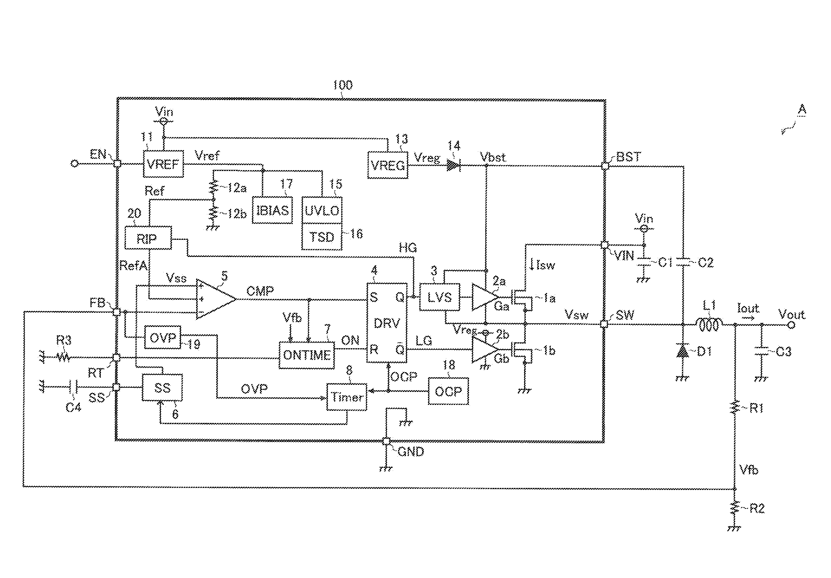
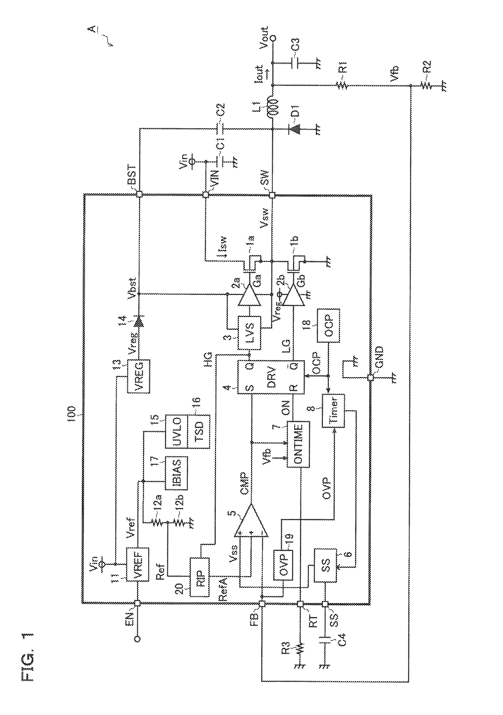
[0057]FIG. 1 is a circuit block diagram that shows a switching power supply device. A switching power supply device A according to the present structural example is a switching power supply device of voltage step-down type that has: a switching power supply IC 100; and discrete components (inductor L, diode D1, resistors R1 to R3, and capacitors C1 to C4) externally connected to the switching power supply IC100, and generates a desired output voltage Vout from an input voltage Vin.

[0058]The switching power supply IC100 has: N channel type MOS [metal oxide semiconductor] field effect transistors 1a and 1b; drivers 2a and 2b; a level shifter 3: a drive control circuit 4; a main comparator 5; a soft start control circuit 6; an on-time setting circuit 7; a timer 8; a reference voltage generation circuit 11; resistors 12a and 12b; a constant voltage generation circuit 13; a diode 14; a low voltage lockout circuit 15; a thermal shutdown circuit 16; an input bias current generation circuit...

second embodiment

[0198]Accordingly, the switching power supply device 1 has a structure that detects the backward flow current to the transistor 1b by using the backward flow detection circuit 30 and forcibly turns off the transistor 1b during a high level duration (from time points t3 to t4) of the skip signal S2. By employing such structure, it becomes possible to obviate the efficiency decline during the light load time.

[0199]Besides, as to the switching power supply device 1 according to the second embodiment, the internal structure of the ripple generation circuit 20 for performing switching stop control at a time of detecting a backward flow current is under review. Hereinafter, a sixth structural example of the ripple generation circuit 20 is described in detail with reference to FIG. 28.

[0200]

[0201]FIG. 28 is a circuit diagram that shows a sixth structural example of the ripple generation circuit 20. The sixth structural example has the substantially same structure as the above first struct...


PUM


Abstract

A switching power supply device has a reference voltage generator for generating a reference voltage, a ripple injector for generating a ripple component by use of a pulse voltage indicating the on/off state of a switching element and injecting the ripple component into the reference voltage, an integrated voltage generator for generating an integrated voltage commensurate with the integrated value of the pulse voltage throughout its on- and off-duty periods, a subtractor for lowering according to the integrated voltage the reference voltage before injection of the ripple component or the supply voltage to a buffer that feeds the ripple injector with the pulse voltage after making its pulse height constant, a comparator for comparing a feedback voltage with the reference voltage after injection of the ripple component, and a switching controller for generating an output voltage from an input voltage by non-linear control by turning on and off the switching element according to the output signal of the comparator.

Description

CROSS-REFERENCE TO RELATED APPLICATIONS[0001]This application is based on the following Japanese Patent Applications, and the contents of which are hereby incorporated by reference:[0002](1) Japanese Patent Application No. 2012-110795 (the filing date: May 14, 2012)[0003](2) Japanese Patent Application No. 2012-150891 (the filing date: Jul. 4, 2012)[0004](3) Japanese Patent Application No. 2012-233776 (the filing date: Oct. 23, 2012)[0005](4) Japanese Patent Application No. 2013-007023 (the filing date: Jan. 18, 2013)BACKGROUND OF THE INVENTION[0006]1. Field of the Invention[0007]The present invention relates to a switching power supply device of non-linear control type.[0008]2. Description of Related Art[0009]FIG. 31A to FIG. 31C are each a circuit block diagram and an operation waveform view that show a conventional example of a switching power supply device employing a non-linear control system; FIG. 31A illustrates a switching power supply device that employs a hysteresis window...

Claims


Application Information

Patent Timeline
IPC IPC(8): H02M3/158H04N5/50
CPCH02M3/1582H04N5/50H04N5/63H02M3/156H04N21/4436
Inventor MURAKAMI, KAZUHIROKAWATA, SHINJISATO, KIMINOBU
Owner ROHM CO LTD
Why Eureka
Try Eureka