Unlock instant, AI-driven research and patent intelligence for your innovation.

Birefringent lens material for stereoscopic image display device and method for producing birefringent lens for stereoscopic image display device

a technology birefringent lens, which is applied in the direction of lenses, other domestic objects, instruments, etc., can solve the problems of inability to apply this material as a birefringent lens material composed of liquid crystal polymer, problems such as the inability to meet the requirements of stereoscopic image display, etc., to achieve good optical characteristics, good durability, good productivity

Active Publication Date: 2013-11-21
DAINIPPON INK & CHEM INC
View PDF2 Cites 8 Cited by
  • Summary
  • Abstract
  • Description
  • Claims
  • Application Information

AI Technical Summary

Benefits of technology

The present invention relates to a birefringent lens material for a stereoscopic image display and a method for producing it. The technical effect achieves good optical characteristics, durability, and productivity by increasing the amount of specific liquid crystal monomers used in the material. The method also reduces the occurrence of alignment defects and improves production efficiency.

Problems solved by technology

However, many different types of liquid crystal polymers exist, and in the case where a cured liquid crystal polymer is simply used as a material of a birefringent lens without studying the material in detail (refer to PTL 1), problems in terms of optical characteristics, durability, productivity, etc. of the lens may occur.
However, this material has problems in terms of optical characteristics and productivity, and thus the application of this material as a birefringent lens material composed of a liquid crystal polymer has not proceeded.

Method used


Image

  • Birefringent lens material for stereoscopic image display device and method for producing birefringent lens for stereoscopic image display device
  • Birefringent lens material for stereoscopic image display device and method for producing birefringent lens for stereoscopic image display device
  • Birefringent lens material for stereoscopic image display device and method for producing birefringent lens for stereoscopic image display device

Examples


example 1

[0062]A polyimide solution for an alignment layer was applied onto a glass substrate having a thickness of 0.7 mm by a spin coating method. The polyimide solution was dried at 100° C. for 10 minutes and then baked at 200° C. for 60 minutes to obtain a coating film. The coating film was subjected to a rubbing treatment. The rubbing treatment was conducted using a commercially available rubbing device.

[0063]The birefringent lens material (1) for a stereoscopic image display of the present invention was applied onto the rubbed substrate by a spin coating method in the state where the birefringent lens material (1) was heated at 70° C. Another substrate that had been subjected to a rubbing treatment was arranged on the resulting coating film so that the rubbing direction of the other substrate is antiparallel to the above-described substrate, and the resulting product was then cooled to room temperature. Subsequently, the product was irradiated with UV light at an intensity of 40 mW / cm2...

examples 2 to 14

[0064]Cured products of the birefringent lens materials for a stereoscopic image display of the invention in Examples 2 to 13 were obtained as in Example 1. Each of the cured products had a film thickness of 50 μm, and the alignment thereof was good. The obtained results are shown in Table 3.

[0065]Each of the birefringent lens materials for a stereoscopic image display of the present invention can be polymerized at room temperature, has a good alignment property, and is good in terms of productivity.

TABLE 3TransitionTransitionCoatingAlignmenttemperaturetemperatureBirefringent lens material fortemperatureat room(solid / (liquidstereoscopic image display(° C.)temperaturenenoΔnliquid crystal)crystal / liquid)Example 1Birefringent lens material (1)80Good1.7011.5370.164−21° C.121° C. for stereoscopic image displayExample 2Birefringent lens material (2)70Good1.6951.5330.162−25° C.95° C.for stereoscopic image displayExample 3Birefringent lens material (3)40Good1.5951.5430.052−30° C.53° C.for s...

example 15

[0067]A polyimide solution for an alignment layer was applied onto a glass substrate having a thickness of 0.7 mm by a spin coating method. The polyimide solution was dried at 100° C. for 10 minutes and then baked at 200° C. for 60 minutes to obtain a coating film. The coating film was subjected to a rubbing treatment. The rubbing treatment was conducted using a commercially available rubbing device.

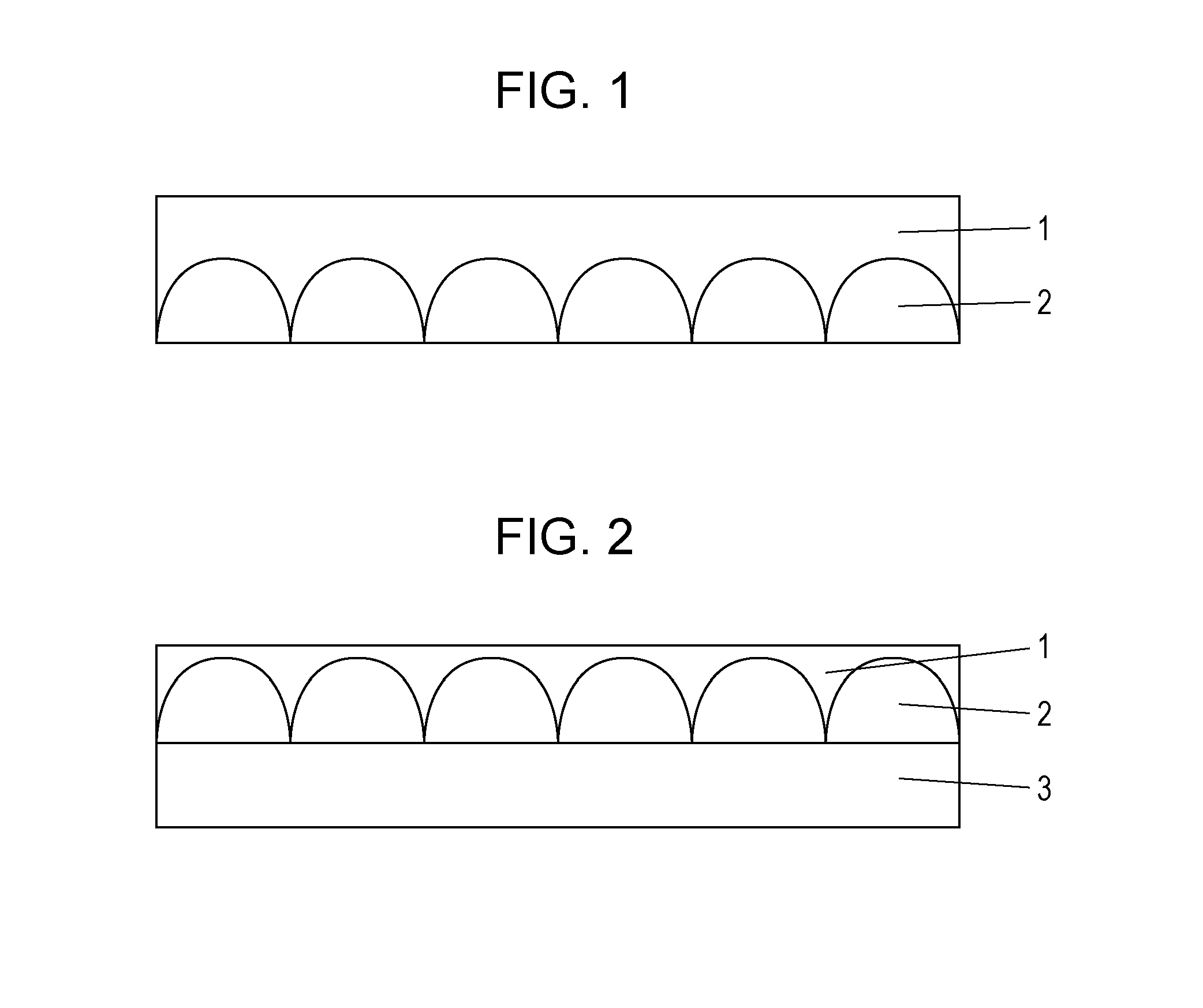
The birefringent lens material (15) for a stereoscopic image display of the present invention was applied onto the rubbed substrate 3 by a spin coating method in the state where the birefringent lens material (15) was heated at 70° C. A resin mold 1 that had been subjected to an alignment treatment was arranged on the resulting coating film so that an alignment direction of the rubbed substrate was parallel to an alignment direction of the resin mold 1, and the resulting product was then cooled to room temperature. Subsequently, the product was irradiated with ultraviolet light at an int...


PUM

PropertyMeasurementUnit
Transition temperatureaaaaaaaaaa
Temperatureaaaaaaaaaa

Abstract

The present invention provides a birefringent lens material for a stereoscopic image display, the birefringent lens material containing two or more liquid crystal compounds each having at least one polymerizable functional group, a birefringent lens for a stereoscopic image display, the birefringent lens being formed by using the lens material, and a method for producing a birefringent lens for a stereoscopic image display using the lens material. The birefringent lens material for a stereoscopic image display and the birefringent lens for a stereoscopic image display of the present invention are good in terms of optical characteristics, durability, and productivity, in particular, productivity. The method for producing a birefringent lens for a stereoscopic image display of the present invention has good productivity.

Description

TECHNICAL FIELD[0001]The present invention relates to a birefringent lens material used for a stereoscopic image display and a method for producing a birefringent lens for a stereoscopic image display.BACKGROUND ART[0002]A stereoscopic image display provides a sense of depth by individually sending substantially two-dimensional images to the right eye and the left eye of a person, allowing the images to be integrated in the brain, and allowing the integrated image to be stereoscopically viewed. For this purpose, it is necessary to individually form images for generating a parallax in advance and to correct the images when the images are sent to the corresponding eyes, or it is necessary to separate a two-dimensional image into an image to be viewed by the right eye and an image to be viewed by the left eye.[0003]In the method for separating a two-dimensional image, it is not necessary to wear polarized glasses or the like for correcting an image and thus a stereoscopic image can be ...

Claims


Application Information

Patent Timeline
IPC IPC(8): G02B1/04G02B30/25G02B30/27
CPCG02B1/041G02B1/04G02B1/08G02B30/25C08L101/12B05D3/067B29C39/006B29C39/123B29C39/22B32B37/182B32B38/0008G02B1/00G02B3/00G02B3/06G02F1/13G02F1/1335G03F7/20C09K19/0403C09K19/04C09K2019/0407C09K2019/0414G02B30/27B29K2035/00B29K2105/0002B29K2105/0079B29K2995/0032B29L2011/0016B32B2305/55B32B2307/42B32B2310/0831B32B2333/04B32B2551/00
Inventor KUWANA, YASUHIROHASEBE, HIROSHI
Owner DAINIPPON INK & CHEM INC
Features
  • R&D
  • Intellectual Property
  • Life Sciences
  • Materials
  • Tech Scout
  • Unparalleled Data Quality
  • Higher Quality Content
  • 60% Fewer Hallucinations
Learn More