Learning method of neural network circuit

a neural network and learning method technology, applied in the field of learning methods of neural network circuits, can solve problems such as the increase of the circuit area of the whole neural network circui

Inactive Publication Date: 2013-11-21
PANASONIC INTELLECTUAL PROPERTY MANAGEMENT CO LTD
View PDF1 Cites 16 Cited by
  • Summary
  • Abstract
  • Description
  • Claims
  • Application Information

AI Technical Summary

Benefits of technology

[0012]In accordance with the present invention, learning operation using pulse ...

Problems solved by technology

However, the neural network circuit which implements the pulse timing model disclosed in...

Method used


Image

  • Learning method of neural network circuit
  • Learning method of neural network circuit
  • Learning method of neural network circuit

Examples


embodiment

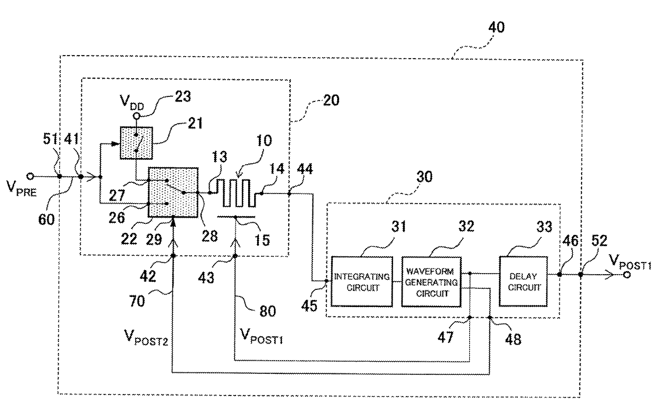
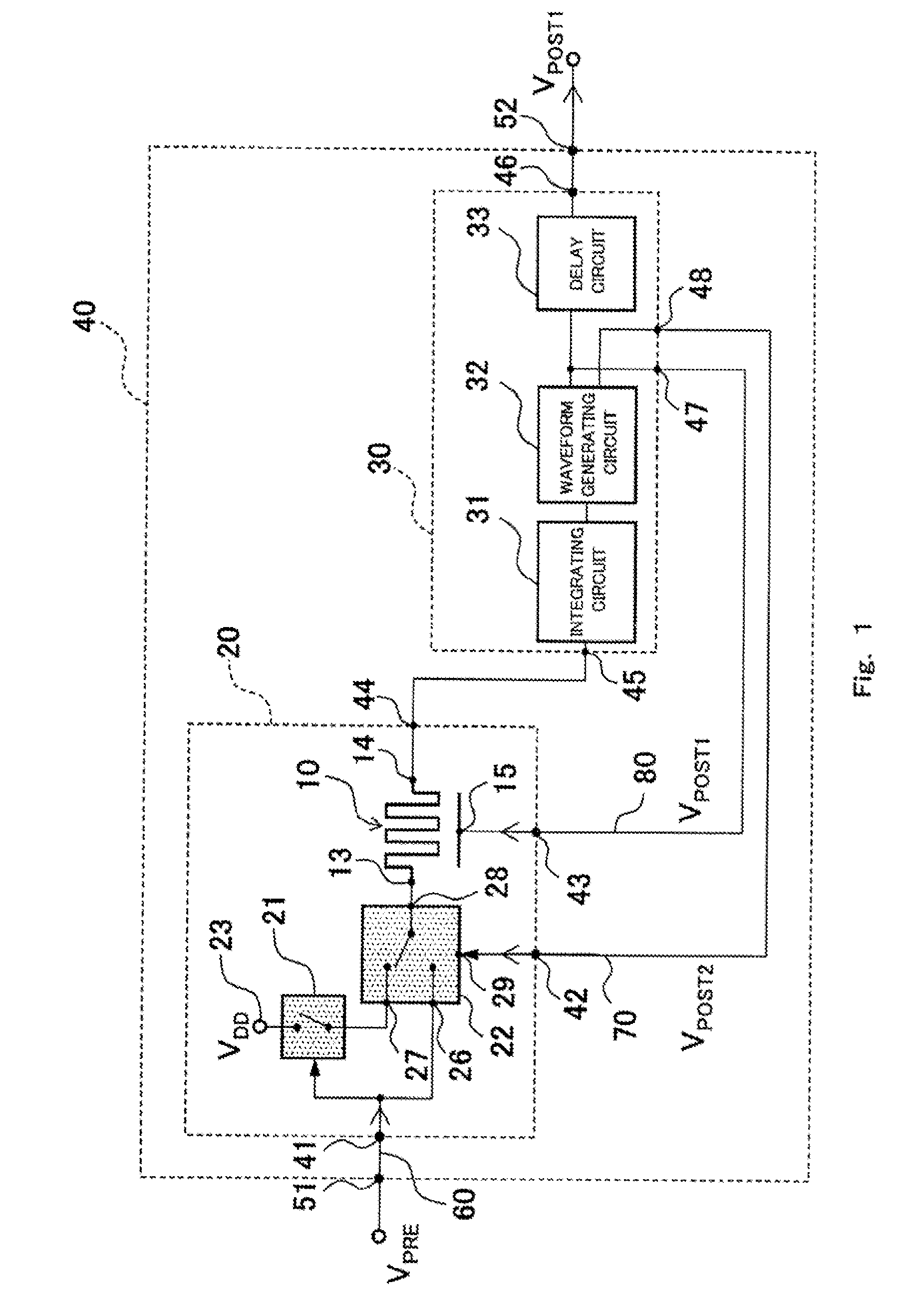
[0069]FIG. 1 is a block diagram showing a neural network circuit element 40 (hereinafter will be sometimes referred to as particular neural network circuit element) according to an embodiment. One neural network circuit element 40 includes at least one input terminal 51, a synapse circuit 20 which is equal in number to the input terminal 51, one neuron circuit 30, and one output terminal 52. As shown in FIGS. 9A and 9B, the neural network circuit is configured to include a plurality of neural network circuit elements 40 which are interconnected. Specifically, the output terminal 52 of the particular neural network circuit element 40 is connected to the input terminal 51 of other neural network circuit elements 40.

[0070]The input terminal 51 of the neural network circuit element 40 is connected to a first input terminal 41 of the synapse circuit 20. An output terminal 44 of the synapse circuit 20 is connected to an input terminal 45 of the neuron circuit 30. A first output terminal 4...

example 1

Fabrication of Variable Resistance Element 10

[0102]An oxide conductive layer comprising a strontium ruthenium oxide (SrRuO3) which was 30 nm in thickness was deposited on a (001) single crystal substrate comprising a strontium titanate (SrTiO3) by pulse laser deposition (hereinafter will be referred to as PLD). A temperature of the substrate during deposition was 700 degrees C. After the deposition, the control electrode 15 was formed by photolithography and ion trimming.

[0103]In a state in which the temperature of the substrate was 700 degrees C., the ferroelectric layer 12 comprising lead zirconate titanate (PZT) (Pb (Zr, Ti) O3) which was 450 nm in thickness was deposited on the SRO by the PLD. After that, the temperature of the substrate was lowered to 400 degrees C. Then, the semiconductive layer 11 comprising zinc oxide (ZnO) which was 30 nm in thickness was deposited on the ferroelectric layer 12.

[0104]After forming a patterned resist on the semiconductive layer 11, a laminat...


PUM


Abstract

A neuron circuit in a neural network circuit element includes a waveform generating circuit for generating a bipolar sawtooth pulse voltage, and a first input signal has a bipolar sawtooth pulse waveform. For a period during which the first input signal is permitted to be input to a first electrode of a variable resistance element, the bipolar sawtooth pulse voltage generated within the neural network circuit element including the variable resistance element which is applied with the first input signal from another neural network circuit element is input to a control electrode of the variable resistance element. The resistance value of the variable resistance element changes due to an electric potential difference between the first electrode and the control electrode, the electric potential difference being generated depending on an input timing difference between a voltage applied to the first electrode and the voltage applied to the control electrode.

Description

CROSS REFERENCE TO RELATED APPLICATION[0001]This is a continuation application under 35 U.S.C. 111(a) of pending prior International application No. PCT / JP2012 / 003491, filed on May 29, 2012.BACKGROUND OF THE INVENTION[0002]1. Field of the Invention[0003]The present invention relates to a learning method of a neural network circuit.[0004]2. Description of the Related Art[0005]At present, computers have been developed remarkably and utilized in various daily scenes. However, so far, development of processing abilities of the computers have been achieved by miniaturization of components (parts) and progresses of algorithms, and basic principles of information processing have not changed. Meanwhile, because of characteristics of processing methods, the computers have a drawback that they are very weak in operations which can be performed easily by humans. For example, the computers are weak in real-time face recognition, understanding of space structures, etc. Processing speeds of these...

Claims


Application Information

Patent Timeline
IPC IPC(8): G06N3/04
CPCG06N3/04G06N3/049G06N3/063
Inventor NISHITANI, YUKANEKO, YUKIHIROUEDA, MICHIHITO
Owner PANASONIC INTELLECTUAL PROPERTY MANAGEMENT CO LTD
Why Eureka
Try Eureka