Novel separator, an electrochemical cell therewith and use thereof therein

a technology of electrochemical cells and separators, which is applied in the direction of cell components, final product manufacturing, sustainable manufacturing/processing, etc., can solve the problems of inability to provide hydrogen at high pressure, expensive compression steps being always necessary, and limited operation range of electrolysis cells, etc., to achieve constant cell temperature, maintain cell ionic conductivity, and reduce cell voltage

Active Publication Date: 2013-12-19
VLAAMSE INSTELLING VOOR TECHNOLOGISCH ONDERZOEK NV VITO
View PDF13 Cites 19 Cited by
  • Summary
  • Abstract
  • Description
  • Claims
  • Application Information

AI Technical Summary

Benefits of technology

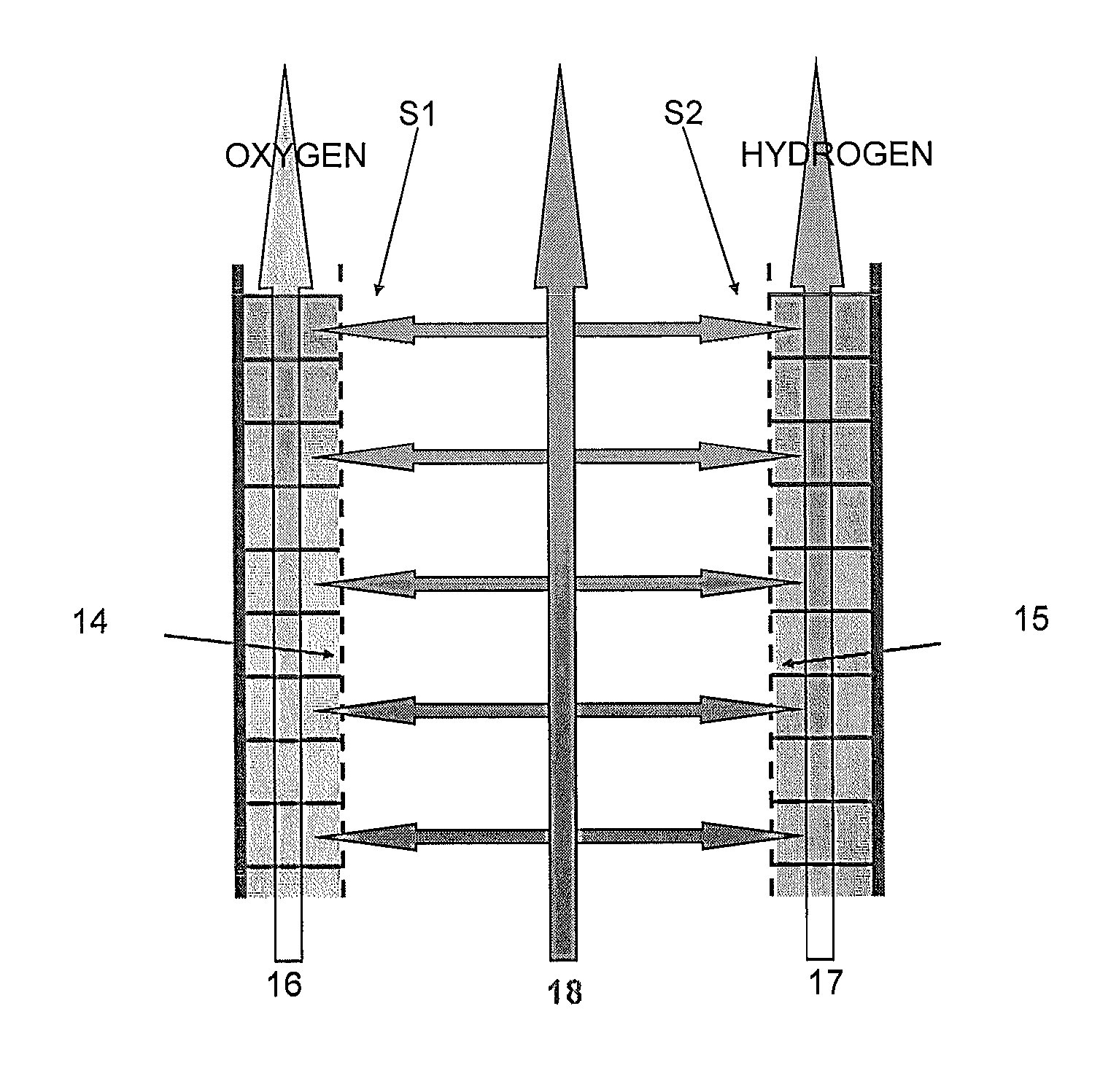
[0022]A still further advantage of the present invention is that the flow of electrolyte through the integrated hollow by-pass channel removes corrosion products, thereby maintaining the ionic conductivity of the cell and enables a constant cell temperature to be maintained.
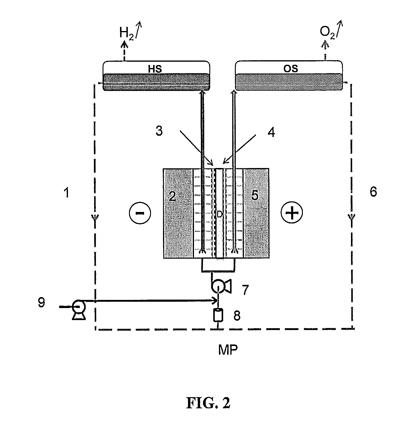
[0023]A still further advantage of the present invention is equalisation of the concentration of the electrolyte in both anolyte and catholyte of electrolytic cells because they are mixed just after they leave gas separators and just before they enter into the third compartment which leads to a slightly lower cell voltage since the electrolyte conductance is highest.
[0024]A still further advantage of the present invention is that the separator elements are sufficiently resilient to follow the contours of the pre-electrodes in the catholyte and anolyte compartments thereby avoiding gas bubbles between the surface of the separators and the respective pre-electrodes and reducing the resistance of the electrochemical cell comprising the separator.
[0025]According to a firs

Problems solved by technology

Prior art alkali water electrolysis cells have a too limited operational range (20 to 100% of the nominal capacity) and cannot provide hydrogen at high pressures, an expensive compression step being always necessary.
However asbestos is a highly carcinogenic substance.
Moreover, the thinnest asbestos diaphragms are 3-4 mm thick, thus limiting the realisable ohmic resistance, and they cannot be used above 85° C. or with aqueous potassium hydroxide concentrations above 30 wt %, making it unsuitable for future applications.
A major problem with candidates to replace asbestos as separator materials is their lack of hydrophilicity, their difficult-to-control manufacturing process and their high associated cost.
None of these materials has been demonstrated to be suitable for future application in electrochemical cells involving the production or consumption of at least one gas.
Such non-reinforced separators have been commercialized as ZIRFON® separators and exhibit good wettability, low ionic resistance and a high bubb

Method used


Image

  • Novel separator, an electrochemical cell therewith and use thereof therein
  • Novel separator, an electrochemical cell therewith and use thereof therein
  • Novel separator, an electrochemical cell therewith and use thereof therein

Examples


examples

Fabrics Used in the EXAMPLES:

[0208]A FC 0360 / 50 PW ethylene-tetrafluorethylene copolymer (EFTE) fabric from NBC Inc. (Liaison Office Europe, Am Isarkanal 21, D-85464 Neufinsing, Germany), which is a 310 μm thick fabric with a mesh opening of 360 μm and an open area of 50% made from 150 μm thick monofilament EFTE, is used in the Comparative Example.

[0209]A V C PO 471 PPS fabric from Vandenstorme Weaving (De Bruwaan, Oudenaarde, Belgium), which is a 2.0 mm thick woven fabric with two faces each having a thickness of 300 μm and a hollow channel 1.48 mm thick in between with the woven fabric having an open area of 50% and being made with monofilament 100 μm thick PPS, is used in the Invention Example.

Separators Used in the EXAMPLES:

[0210]Two types of separator were used a single layer 550 μm thick reinforced Zirfon® Perl 550 HP single-layer membrane separator produced as described in WO 2009 / 147084A1 by casting a dope containing as solid constituents 85% by weight of zirconia (ZrO2) and...


PUM

PropertyMeasurementUnit
Temperatureaaaaaaaaaa
Pore sizeaaaaaaaaaa
Pressureaaaaaaaaaa

Abstract

An ion-permeable web-reinforced separator, said ion-permeable web-reinforced separator comprising two separator elements separated by an (optionally integrated) substantially hollow by-pass channel, wherein the separator elements each comprise a binder and a metal oxide or hydroxide dispersed therein and the separator elements have a bubble point of at least 1 bar (0.1 MPa) and a back-wash resistance of at least 1 bar (0.1 MPa) and optionally have a specific resistance less than 4 Ω-cm at 30° C. in 6M potassium hydroxide solution; an electrochemical cell involving the production or consumption of at least one gas, said electrochemical cell comprising said ion-permeable web-reinforced separator; and the use thereof in an electrochemical cell involving the production or consumption of at least one gas.

Description

CROSS REFERENCE TO PRIOR APPLICATIONS[0001]This application is a Continuation-In-Part of International Application No. PCT / EP2012 / 053376, filed Feb. 28, 2012, which claims priority to European Patent Application No. 11156178.3 filed Feb. 28, 2011, and U.S. Provisional Application No. 61 / 447,145, filed Feb. 28, 2011, the entire contents of which are incorporated herein by reference.TECHNICAL FIELD OF THE INVENTION[0002]The present invention relates to a novel separator and an electrochemical cell, for example a high pressure alkaline water electrolysis cell, and an air fuel cell comprising the novel separator.BACKGROUND OF THE INVENTION[0003]Hydrogen is the only energy source with zero carbon dioxide emission. Electrical energy produced from wind, sun and wave power can be converted into hydrogen by the electrolysis of water and the hydrogen produced can be used to generate energy either in proton exchange membrane fuel cells (PEMFC's) or by combustion with the only by-product being ...

Claims


Application Information

Patent Timeline
IPC IPC(8): C25B13/02H01M8/02
CPCC25B13/02H01M8/0258C25B1/04C25B13/04C25B9/05H01M8/0239H01M8/0245H01M8/08C08J5/22H01M8/0215H01M8/0243H01M8/0252H01M8/083Y02E60/36Y02E60/50Y02P70/50
Inventor DOYEN, WILLYALVAREZ GALLEGO, YOLANDA
Owner VLAAMSE INSTELLING VOOR TECHNOLOGISCH ONDERZOEK NV VITO
Why Eureka
Try Eureka