

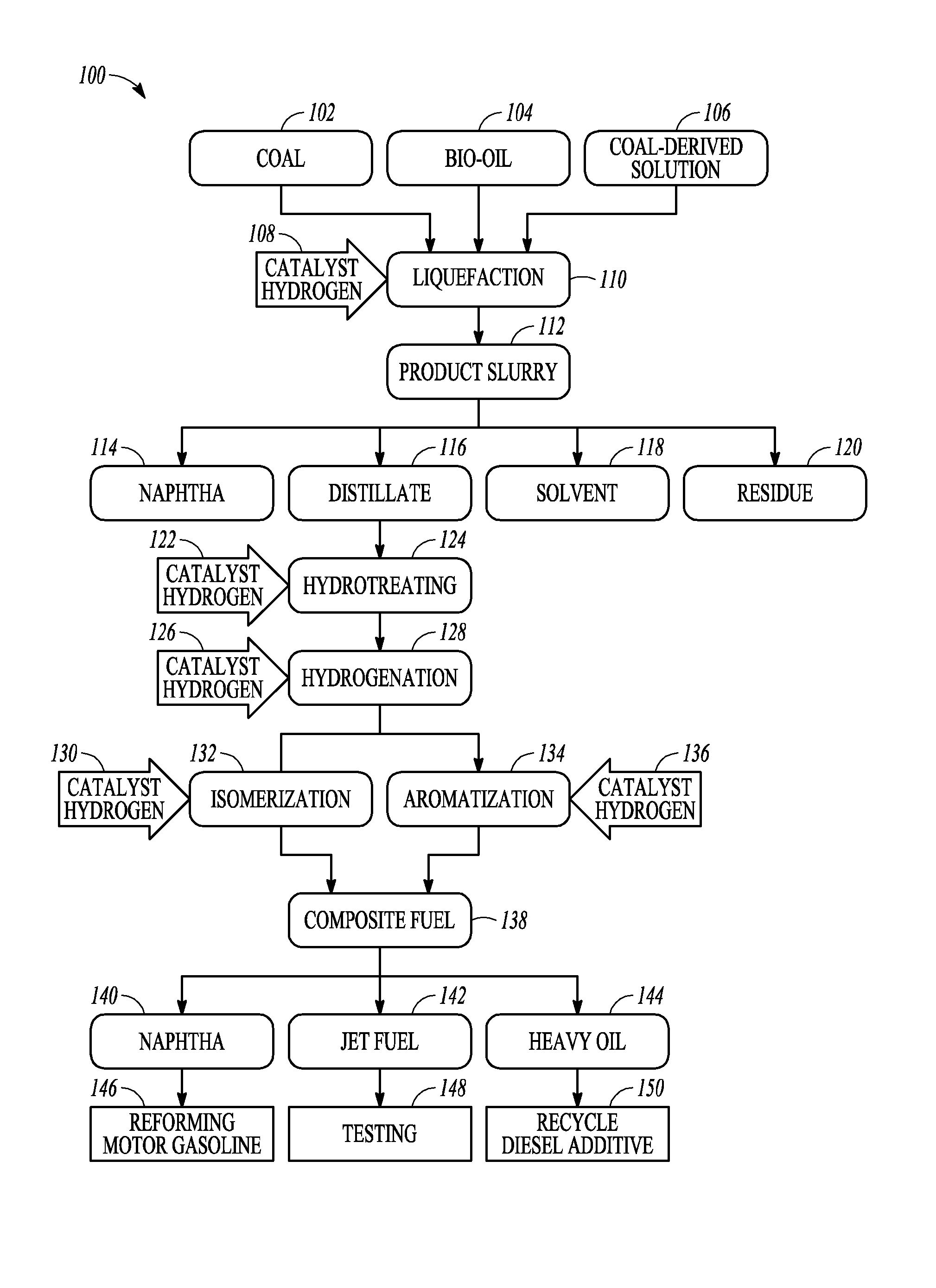
Liquefaction of carbonaceous material and biomass to produce a synthetic fuel
a carbonaceous material and synthetic fuel technology, applied in the direction of fuels, organic chemistry, chemistry apparatus and processes, etc., can solve the problems of limited and non-renewable resources of petroleum, the most competitive technologies do not produce all the key constituents needed to produce synthetic fuels, and the extraction, transportation and refining of petroleum can be problematic, so as to achieve less energy or valuable materials, less complex, and less carbon footprint
- Summary
- Abstract
- Description
- Claims
- Application Information
AI Technical Summary
Benefits of technology
Problems solved by technology
Method used
Image

Examples
example 1
Production of Solvent
[0111]Initial tests were performed to produce test coal-derived solvent for the liquefaction runs. A slurry including coal tar-derived solvent (b.p., 343°-538° C.) was formed with predried pulverized coal. The slurry was contacted with a commercial presulfided CoMo catalyst under a hydrogen pressure in the autoclave. The experiment was run at 450° C., a pressure of 78 atmo, and under a constant flow of 13 scfh hydrogen for 60 minutes. The product slurry was distilled to produce test coal-derived solvent (b.p., 343°-538° C.). The liquefaction procedure was repeated using the solvent generated to produce solvent using a recycled solvent.
example 2
Runs 1-3: Liquefaction of Canola Oil and Coal
[0112]After a desired quantity of the test coal-derived solvent was generated using the recycled solvent, a slurry including coal, canola oil, vacuum bottoms (e.g., hydrocarbon waxes similar to petroleum residue left after refining of crude oil) and coal-derived solvent (having a mass ratio of 0.8:0.2:1.0:1.0), and 0.03 wt % of commercial presulfided CoMo catalyst was placed in the autoclave. The sulfur in the coal was enough to keep the catalyst sulfided during the run. The reactor was charged with 70 atm hydrogen pressure and placed in the heating jacket. The reactor was heated to 350° C. to convert triglycerides into paraffins via hydrolysis and decarbonylation and then heated and pressurized to the temperature and pressure shown in Table 1, which also shows other operating conditions. A constant hydrogen flow was maintained throughout the run. The runs were carried out in hydrogen flow-through mode (13.18 scfh). At the end of the run,...
example 3
Runs 4-5: Liquefaction of Algae Oil and Coal
[0114]Coal, algae oil, and catalyst were slurried in a coal-derived solvent. A similar procedure to that used in Example 2 was used. Operating conditions and yield data are given in Tables 1 and 2.
PUM
| Property | Measurement | Unit |
|---|---|---|
| mass ratio | aaaaa | aaaaa |
| pressure | aaaaa | aaaaa |
| temperature | aaaaa | aaaaa |
Abstract
Description
Claims
Application Information