
Photorefractive composition comprising electrolytes in a photorefractive layer and method of making thereof

a photorefractive layer and electrolyte technology, applied in the field of photorefractive composition and photorefractive device, can solve the problems of complex synthesis of tpd acrylate monomer, difficult to obtain, and inability to readily commercialize tpd acrylate monomer, so as to improve grating response and grating decay time, and reduce the grating response time and/or the grating decay time

Inactive Publication Date: 2013-12-26
NITTO DENKO CORP
View PDF2 Cites 1 Cited by
  • Summary
  • Abstract
  • Description
  • Claims
  • Application Information

AI Technical Summary

Benefits of technology

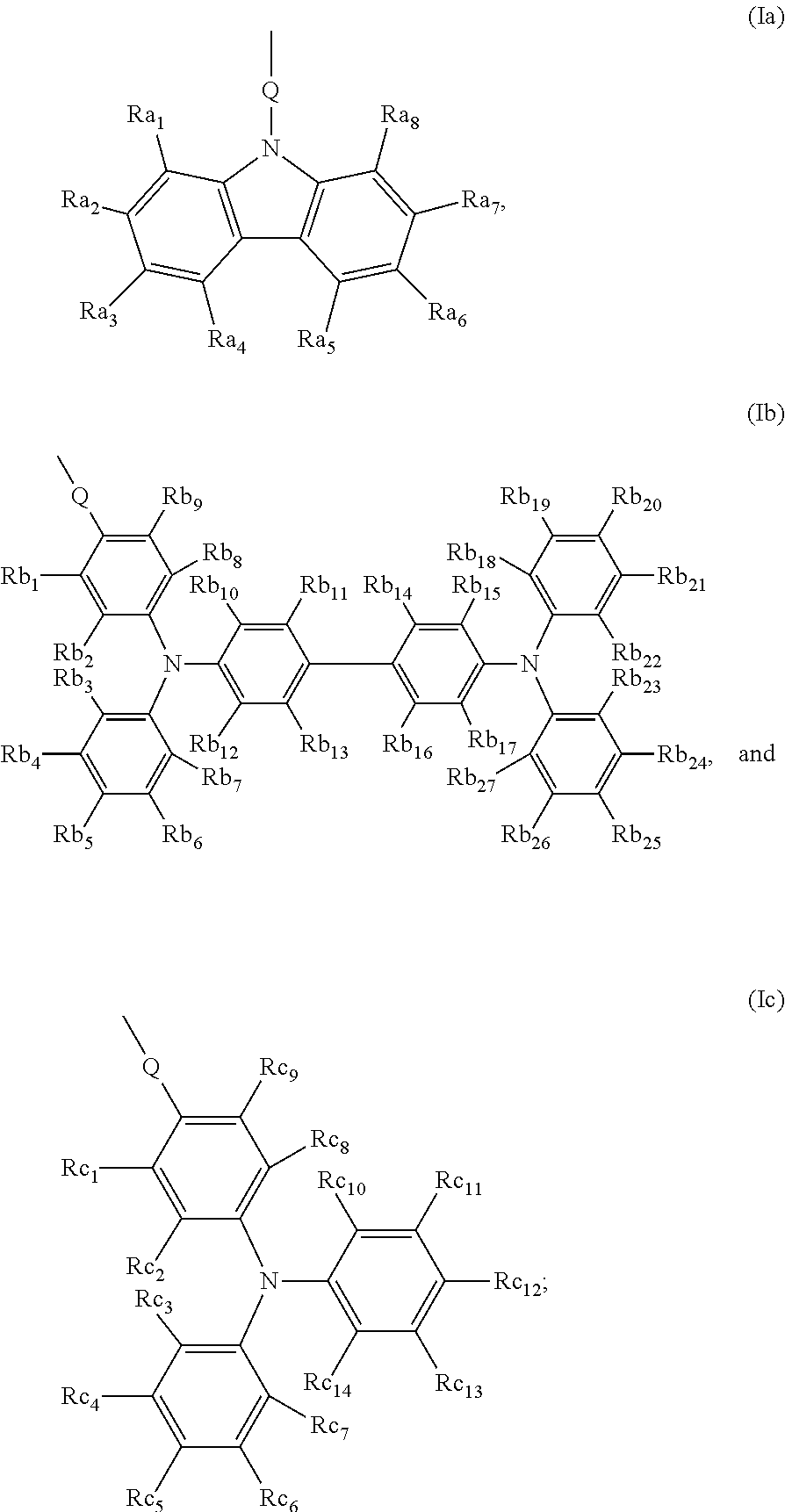
This patent describes a new type of polymer that shows improved performance when used in photorefractive compositions. These polymers are easier and less expensive to make than previous options. The patent also mentions the surprise discovery that these polymers can still generate sufficient photorefractive behavior without needing additional charge transport moieties. The patent also discusses the inclusion of electrolytes in the photorefractive composition, which can help reduce the time it takes for the composition to switch between different states. Without electrolytes, the grating response time was measured to be about 8,000 seconds and the grating decay time was measured to be about 50 seconds. Overall, this patent offers a new way to design photorefractive compositions that are more efficient and cost-effective.

Problems solved by technology

However, the TPD acrylate monomer is not readily commercially available and may be difficult to obtain.
Additionally, the synthesis of TPD acrylate monomer is complicated, requiring multiple, e.g. nine to ten, steps.
As such, the difficulties of synthesizing TPD based polymers render their price quite high.
The complicated synthesis represents a hurdle for manufacturing or large scale production of photorefractive devices.

Method used


Image

  • Photorefractive composition comprising electrolytes in a photorefractive layer and method of making thereof
  • Photorefractive composition comprising electrolytes in a photorefractive layer and method of making thereof
  • Photorefractive composition comprising electrolytes in a photorefractive layer and method of making thereof

Examples


example 1

Preparation of Photorefractive Devices

[0083]A photorefractive composition testing sample was prepared comprising two ITO-coated glass electrodes, and a photorefractive layer. The components of the photorefractive composition were approximately as follows:

(i) Matrix polymer APC:~33 wt %(ii) Prepared chromophore of 7F-DCST~33 wt %(iii) Ethyl carbazole plasticizer~33 wt %(iv) Electrolyte 10-methyl-9-phenylacridiniumlisted in Table 1perchlorate (MPP)

[0084]To prepare the composition, the components listed above were dissolved in dichloromethane with stiffing and then dripped onto glass plates at 60° C. using a filtered glass syringe. The composites were then heated to 60° C. for five minutes and then vacuumed for five more minutes. The composites were then heated to 150° C. for five minutes and then vacuumed for 30 seconds. The composites were then scrapped and cut into chunks.

[0085]Small portions of this chunk were taken off and sandwiched between indium tin oxide (ITO) coated glass pla...

example 2-9

[0088]A photorefractive device was obtained in the same manner as in Example 1 except that the electrolyte doping percentage and photorefractive layer thickness were different. The amount of electrolyte and photorefractive layer thicknesses are provided in Table 1.

examples 10-11

[0092]A photorefractive device was obtained in the same manner as in Example 1 except that the polymer in the photorefractive layer is PMMA. The electrolyte doping percentage and photorefractive layer thicknesses are provided in Table 2.


PUM

PropertyMeasurementUnit
wavelengthaaaaaaaaaa
grating response timeaaaaaaaaaa

Abstract

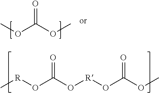
A photorefractive composition and a photorefractive device comprising the composition are disclosed. The composition is configured to be photorefractive upon irradiation by a laser having a wavelength in the visible light spectrum and comprises a polymer, a non linear optical chromophore, a plasticizer, and an electrolyte. In an embodiment, the percentage of polymer recurring units that comprise a charge transport moiety is less than 30%. In an embodiment, the electrolyte comprises one or more of ammonium salts, heterocyclic ammonium salts, and phosphonium salts. In an embodiment, the polymer is selected from the group consisting of polycarbonate, polyurea, polyurethane, poly(meth)acrylate, polyester, polyimide, and combinations thereof. Preferably, the composition has a diffraction efficiency of about 25% or greater upon irradiation with a visible light laser.

Description

CROSS-REFERENCE TO RELATED APPLICATIONS[0001]The present application claims priority under 35 U.S.C. §119(e) to U.S. Provisional Application No. 61 / 445,917 filed on Feb. 23, 2011, the disclosures of which is incorporated by reference herein in its entirety.STATEMENT REGARDING FEDERALLY SPONSORED R&D[0002]This invention was made with government support under FA8650-10-C-7034 awarded by the Office of the Director of National Intelligence (ODNI), Intelligence Advance Research Projects Activity (IARPA), through the Air Force Research Laboratory (AFRL). The government has certain rights in the invention.BACKGROUND OF THE INVENTION[0003]1. Field of the Invention[0004]The invention relates to a photorefractive composition and a photorefractive device comprising the composition, wherein the composition is configured to be photorefractive upon irradiation by a laser having a wavelength in the visible light spectrum, wherein the composition comprises a polymer, a chromophore, a plasticizer, a...

Claims


Application Information

Patent Timeline
Patent Type & Authority Applications(United States)
IPC IPC(8): G02B1/04G11B7/24044
CPCG02B1/04G02F1/3617G03H1/02G03H2001/0264G03H2260/54G11B7/24044
Inventor LIN, WEIPINGGU, TAOCAI, JIEHSIEH, WAN-YUNSUTIN, ALLAHU, YUFENWANG, PENGYAMAMOTO, MICHIHARU
Owner NITTO DENKO CORP
Learn More