Micro-structured biomaterials and fabrication methods therefor

Active Publication Date: 2013-12-26
RGT UNIV OF CALIFORNIA
View PDF0 Cites 53 Cited by
  • Summary
  • Abstract
  • Description
  • Claims
  • Application Information

AI Technical Summary

Benefits of technology

[0017]In other embodiments, multilayer constructs are fabricated with DMD-PP by stacking the single-layer constructs with alternating layers of vertical connecting posts. The Poisson's ratio of the single-layer and multilayer constructs can be determined from strain

Problems solved by technology

Although yield strength and stiffness (elastic modulus) are of vital importance in providing the scaffold with satisfactory mechanical integrity, and show power-law behavior with regards to porosity, it does not fully characterize a construct's elastic behavior since it only describes deformation in the loading direction and does not address deformations in the transverse

Method used


Image

  • Micro-structured biomaterials and fabrication methods therefor
  • Micro-structured biomaterials and fabrication methods therefor
  • Micro-structured biomaterials and fabrication methods therefor

Examples


Example

EXAMPLE 1

Preparation of Photocurable Monomers

[0094]Poly(ethylene glycol)diacrylate (PEGDA, Mw=700), acrylic acid (AA), and 2,2,6,6-tetramethylpiperidine 1-oxyl (TEMPO, free-radical quencher) were obtained from Sigma-Aldrich. Photoinitiator Irgacure 2959 and TINUVIN 234 UV-dye were obtained from Ciba Chemistry. TINUVIN 234 is a UV-absorbing agent, which was used to reduce the curing depth of the monomers and adjust the thickness of the microstructures in the DMD-based layer-by-layer fabrication process. TEMPO, on the other hand, enhances the contrast of the UV-curing process and optimizes feature resolution at the projection plane. 1% (w / v) Irgacure 2959, 0.15% (w / v) of TINUVIN 234, and 0.01% (w / v) of TEMPO were added to the PEGDA monomer and mixed thoroughly.

Example

EXAMPLE 2

Digital Micro-Mirror Array Device (DMD) Fabrication

[0095]FIG. 6 shows a schematic of the DMD-based system used to fabricate the auxetic biomaterial scaffolds. Two-dimensional (2D) graphics models of the scaffold layers were designed in computer-aided drafting (CAD) software (AutoCAD LT 2006; Autodesk, Inc., San Raphael, Calif., USA). CAD models in the drawing interchange format (DXF file extension, outputted from AutoCAD) were converted into standard bitmap format (BMP file extension) and exported to LabVIEW software (National Instruments, Austin, Tex., USA), which was used to control the DMD system. The bitmap graphics files were used as virtual photomasks during the DMD layer-by-layer photocuring process.

[0096]A servo-stage 60 with X, Y and Z axis motion was positioned 100 μm below a transparent quartz plate 62 (quartz microscope slide), leaving a 100 μm gap 61 between the plate and the stage. 10 μL of photocurable prepolymer was injected into the gap 61 with a syringe pu...

Example

EXAMPLE 3

Stress-Strain Finite Element Simulations

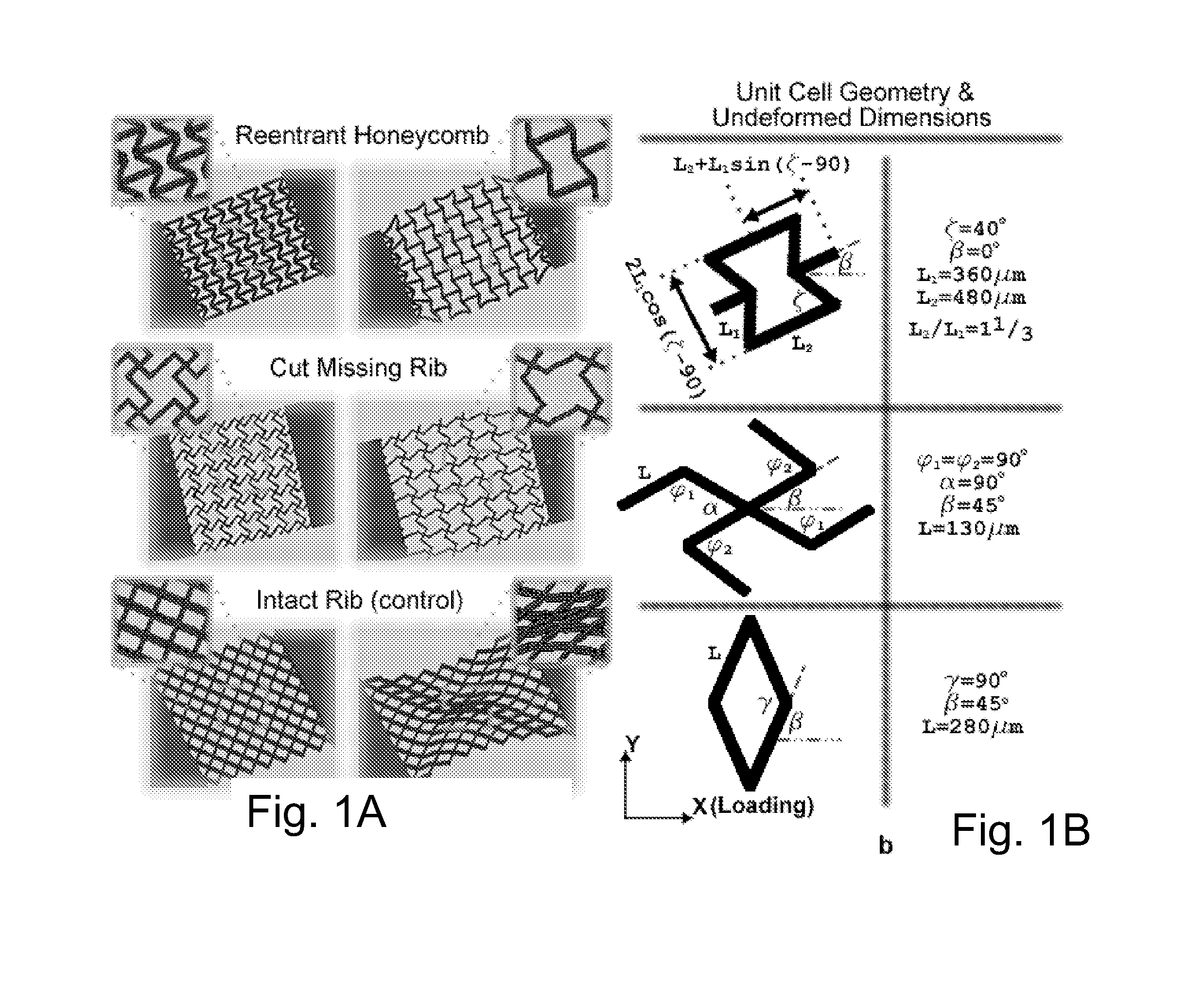
[0098]AutoCAD LT was used to design the 2D scaffold layers with the desired unit-cell structures. The unit-cell structures were designed from analytical models proposed in the literature. The 2D models were imported into SOLIDWORKS® 3D CAD software (SOLIDWORKS® 2009, Dassault Systèmes SolidWorks Corp., Concord, Mass., USA) and extruded to form 3D models of the single-layer sheets. The 3D models were utilized to simulate the elastic stress-strain (deformation) behavior of the single-layer PEG constructs using finite element analysis (also conducted with SOLIDWORKS®; FIGS. 10E and 10FA), taking into account the material properties of the PEG. The simulations allowed us to determine if the unit-cell structures would, theoretically, yield auxetic behavior as desired. The simulations were performed in the same way in which the strain experiments were conducted, i.e., where one of the rectangular side-blocks was fixed while an axial tensile...


PUM

PropertyMeasurementUnit
Ratioaaaaaaaaaa
Microstructureaaaaaaaaaa

Abstract

Techniques, systems, apparatus and material are disclosed for fabricating a micro-structured biomaterial. In one aspect, a micro-structured biomaterial includes a three-dimensional solid-phase micro-cellular biomaterial that exhibits a negative Poisson ratio that is tunable in magnitude.

Description

RELATED APPLICATIONS[0001]This application claims priority to U.S. Provisional Application No. 61 / 416,272, filed on Nov. 22, 2010, which is hereby explicitly incorporated by reference herein in its entirety.GOVERNMENT INTERESTS[0002]This invention was made, in part, with government support under Grant No. R01EB012597 from the National Institute of Biomedical Imaging and Bioengineering (National Institutes of Health (NIH)). The government has certain rights in the invention.FIELD OF THE INVENTION[0003]This invention relates to devices, techniques and material related to micro-structured biomaterials, and more particularly relates to auxetic micro-structured biomaterials, methods to fabricate these biomaterials and uses of these materials.BACKGROUND OF THE INVENTION[0004]Tissue engineering has been defined as an interdisciplinary field that applies the principles of engineering and life sciences toward the development of biological substitutes that restore, maintain, or improve tissue...

Claims


Application Information

Patent Timeline
IPC IPC(8): C12N5/00B29C67/00
CPCC12N5/00B29C67/0081A61L27/14A61L27/40A61L27/52A61L27/56A61L2400/08A61L2400/12A61L2400/18B29C64/165B33Y80/00
Inventor SOMAN, PRANAVCHEN, SHAOCHENFOZDAR, DAVID
Owner RGT UNIV OF CALIFORNIA
Why Eureka
Try Eureka