Refrigerant repelling surfaces

a technology of refrigerant and surface, which is applied in the field of refrigerant repelling surfaces, can solve the problems of increasing the contact angle of liquid droplets on the surface when the atmosphere is substantially vaporized refrigerant, and many conventional systems suffer from the limitation of air present in the atmosphere of heat transfer systems, so as to increase the contact angle of liquid droplets on the surface, increase condensation rate, and increase the effect of heat transfer coefficien

Inactive Publication Date: 2014-01-02
THE BOARD OF TRUSTEES OF THE UNIV OF ILLINOIS
View PDF12 Cites 9 Cited by
  • Summary
  • Abstract
  • Description
  • Claims
  • Application Information

AI Technical Summary

Benefits of technology

The patent text describes methods and devices related to heat transfer, specifically by dropwise condensation of a refrigerant vapor on a surface. The surface is designed to repel refrigerant, and various factors such as pressure, temperature, and composition of the atmosphere can affect the refrigerant-repellency of a surface. The invention also involves using nanoparticles on the surface to enhance droplet mobility, condensation rate, and heat transfer coefficient. The nanoparticles form a network of "walls" surrounding lower elevation features, creating a "waffle" pattern. Overall, the invention allows for precise control over operating parameters and maximizes the contact angle of droplets on the surface, resulting in increased repellency to refrigerant vapor and improved heat transfer efficiency.

Problems solved by technology

In addition, many conventional systems suffer from the limitation of having air present in the atmosphere of the heat transfer system.
In these cases, increasing the contact angle of a liquid droplet on a surface when the atmosphere is substantially vapor of the refrigerant may be more difficult than for a droplet exposed to an atmosphere which is essentially air.

Method used


Image

  • Refrigerant repelling surfaces
  • Refrigerant repelling surfaces
  • Refrigerant repelling surfaces

Examples


example 1

Surface Tension and Contact Angle Calculations

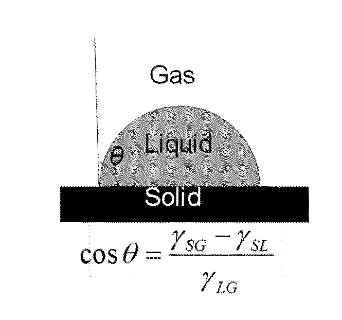
[0097]Equations 1 and 2 give relationships between the flat surface contact angle and the relevant surface free energies and the variation in the surface free energy with temperature.

Cos(θC)=γSG-γSLγLV(Equation1)γ(T)=γ(T0)+Tcγ*(ΔT)(Equation2)

[0098]Where θc: Flat surface contact angle, γLV: Surface tension of water, γSG: Surface free energy (SFE) of surface (e.g. PTFR), γSL: SFE between surface and water, γ(T0): Value of γ at temperature T0., TCγ: Temperature coefficient of the substance., ΔT: (T0−T).

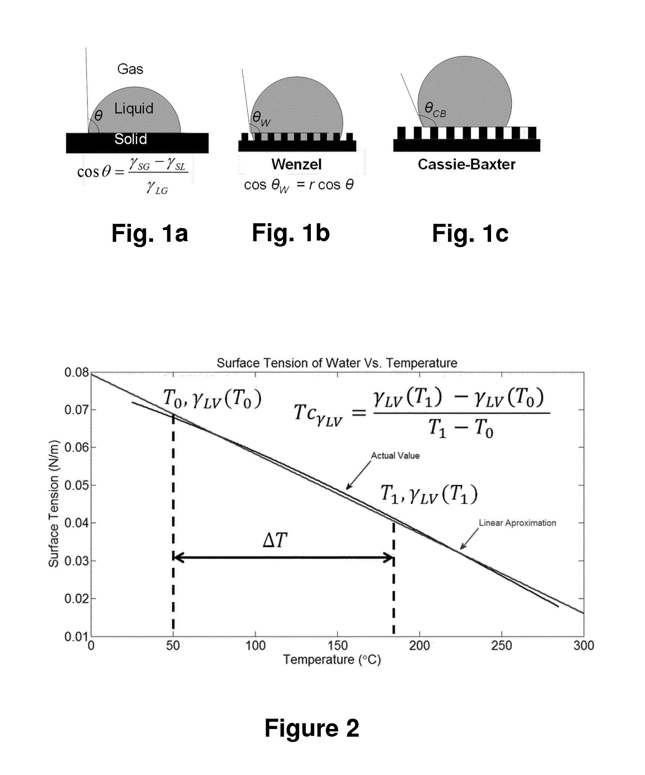
[0099]FIG. 1a illustrates the contact angle on a flat surface; in FIG. 1a θ is equivalent to θc in equation 1.

[0100]FIG. 2 shows water surface tension as a function of temperature.

Cos(θint)=γSG(Tint)-γSL(Tint)γLG(Tint)(Equation3)Cos(θcrit)=γSG(Tcrit)-γSL(Tcrit)γLG(Tcrit)(Equation4)TcγSL=γSL(Tcrit)-γLV(Tint)Tcrit-Tint(Equation5)

[0101]Where γSLcrit: Critical surface tension. Defined as Cos(θc)=1 @ γLV (Tcrit)=γcrit, Tcrit: Temperature where γLV...

example 2

Measurements for Water and Oleic Acid

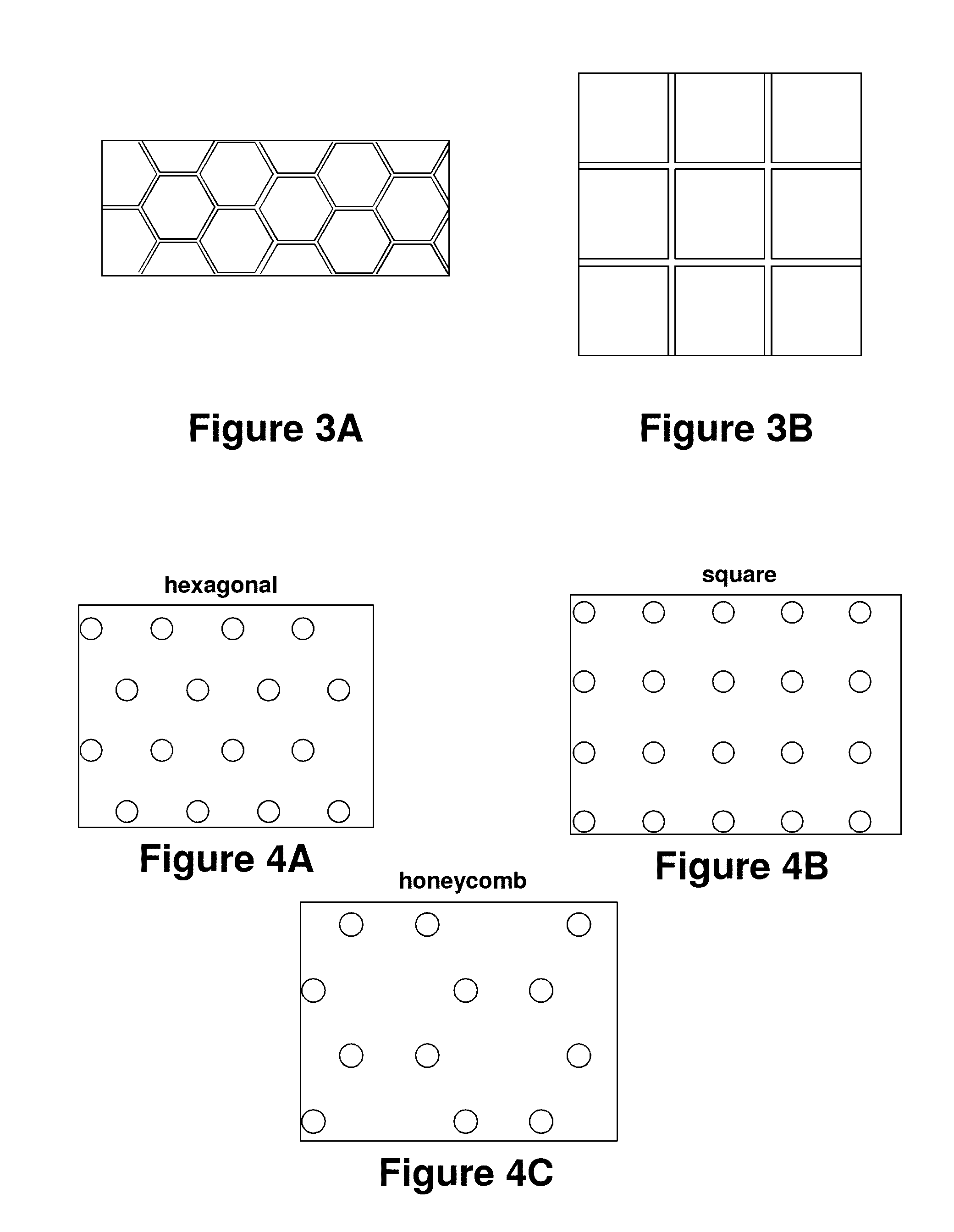
[0103]FIGS. 3A-B and 4A-C schematically illustrate some of the waffle and pillar surface textures fabricated for testing. FIG. 3 is a schematic top view of a hexagonal waffle structure (FIG. 3A) and a grid-like waffle structure (FIG. 3B). FIG. 4 is a schematic top view of different configurations of pillar elements: hexagonal arrangement (FIG. 4A), square arrangement (FIG. 4B), and honeycomb arrangement (FIG. 4C).

[0104]Tables 3 and 4 respectively provide additional information about waffle and pillar surface textures. In Table 2, h is element height, p is pitch and w is width of square or hexagonal depression. In Table 4, A is elements per area p2, d is diameter of the pillar, p is pitch, and h is element height.

TABLE 3Square Wafflesh (μm)p(μm)w (μm)32220Hexagonal Wafflesh (μm)p(μm)w (μm)31210

TABLE 4Square PillarsAd (μm)h (μm) p (μm)15050100Hexagonal PillarsAd (μm)h (μm) p (μm)1.5750300100

[0105]FIG. 5 shows an experimental setup used for contact ...

example 3

Measurements for HC-200

[0129]The contact angle of halocarbon oil HC-200 was measured on smooth and square waffle patterns. The experimental methods were the same as above, with only the liquid type being different. HC-200 is a liquid polymer oil with the chemical name chlorotrifluoroethylene. HC-200 has a surface tension about 0.025 N / m, which is lower than the surface tension for oleic acid. Table 9 shows the results, where the square waffle patterns are oleophobic, while a smooth surface of the same material is oleophillic. In Table 9, w is feature width, p is microstructure period, and d is feature depth.

TABLE 9wpdOilPatternLiquidμmμmμmCA°SmoothHC 200——— 40Square WafflesHC 20020220.3122

[0130]FIG. 27 shows images of halocarbon 200 oil on ZnO particle coated slides; these images illustrate the change in contact angle over 20 seconds. Image taken at 22° C. and 100. 3 kPa.


PUM


Abstract

Methods and devices for dropwise condensation of a refrigerant vapor on a surface are provided. The surface and various aspects of the system are configured to ensure the surface is refrigerant repelling, enhances droplet mobility, increases condensation rate and / or increases heat transfer rate. The refrigerant repelling surface may be configured so that a refrigerant that may normally wet a flat non-textured surface is instead repelled

Description

CROSS-REFERENCE TO RELATED APPLICATIONS[0001]This application claims the benefit of U.S. Provisional Application 61 / 661,701 filed Jun. 19, 2012, which is hereby incorporated by reference to the extent not inconsistent with the disclosure herein.STATEMENT REGARDING FEDERALLY SPONSORED RESEARCH OR DEVELOPMENT[0002]This invention was made with government support under contract number N00014-12-1-0014 awarded by the Office of Naval Research. The government has certain rights in the invention.BACKGROUND[0003]For a liquid droplet on a solid substrate, the contact angle may be defined as the interior angle formed by the substrate and the tangent to the interface between the liquid and gas or vapor at the apparent intersection of the substrate, liquid and gas or vapor phases (see FIG. 1a). The dimension of the droplet is often comparable to or smaller than the capillary length of the liquid. The contact angle may be measured or calculated from images of the droplet on the substrate. The sub...

Claims


Application Information

Patent Timeline
IPC IPC(8): F25B39/04
CPCF25B39/04F25B2400/121F28F13/04F28F13/187
Inventor KING, WILLIAM, P.
Owner THE BOARD OF TRUSTEES OF THE UNIV OF ILLINOIS
Why Eureka
Try Eureka