
Heat radiation reflective film and method for producing the same, and heat radiation reflector

Active Publication Date: 2014-01-02
KONICA MINOLTA INC
View PDF17 Cites 7 Cited by
  • Summary
  • Abstract
  • Description
  • Claims
  • Application Information

AI Technical Summary

Benefits of technology

The present invention provides a heat radiation reflective film that has high heat radiation reflectance and good adherence properties, and can have a large surface area while de-emphasizing certain visible reflected lights. This film can be produced using a specific method. Additionally, the invention provides a heat radiation reflector that includes this film.

Problems solved by technology

The conventional heat radiation reflective film includes a problem that most of the interfaces between the layers are distinct, a problem that the bond strength between the layers is low, and a problem that application of a high peel force results in delamination of layers.

Method used


Image

  • Heat radiation reflective film and method for producing the same, and heat radiation reflector
  • Heat radiation reflective film and method for producing the same, and heat radiation reflector
  • Heat radiation reflective film and method for producing the same, and heat radiation reflector

Examples


examples

[0179]Now, the present invention will be specifically described with reference to examples, although the present invention is not limited thereto. As used in the examples, “part” and “%” refers to “parts by mass” and “percent by mass” respectively, unless otherwise specified.

example i

Preparation of Coating Solution 1

[0180]22.5 of a 5.0% by mass aqueous solution of acid-treated gelatin was admixed, in small portions with stirring, with 20.2 g of 30.0% by mass silica oxide sol with a volume average particle diameter of 20 nm (silicon dioxide particles available under the trade name of Silicadol 20P from Nippon Chemical Industrial Co., Ltd.). Then 0.043 g of 5.0% by mass 2-LB-500E from NOF Corp. as a surfactant was added, and pure water was added to bring the volume to 75 ml. to prepare a coating solution 1.

[0181](Preparation of Coating Solution 2)

[0182]22.5 g of a 5.0% by mass aqueous solution of acid-treated gelatin was admixed, in small portions with stirring, with 20.2 g of 15.0% by mass titanium oxide sol with a volume average particle diameter of 5 nm (rutile-type titanium oxide particles available under the trade name of SRD-W from Sakai Chemical Industry Co., Ltd.). Then 0.043 g of 5.0% by mass 2-DB-500E from NOF Corp. as a surfactant was added, and pure wa...

example ii

Preparation of Coating Solution 3

[0216]11.5 g of a 5.0% by mass aqueous solution of collagen peptide available under the trade name of SCP-5200 from Nitta Gelatin Inc. was admixed, in small portions with stirring, with 20.2 g of 15.0% by mass titanium oxide sol with a volume average particle diameter of 5 nm (rutile-type titanium oxide particles available under the trade name of SPD-W from Sakai Chemical Industry Co., Ltd.). Then 15 g of 2.5% by mass tamarind seed gum was added, followed by 0.043 g of 5.0% by mass 2-DB-500E from NOF Corp. as a surfactant. Pure water was added to bring the volume to 50 ml to prepare a coating solution 3.

[0217](Preparation of Coating Solution 4)

[0218]11.5 g of a 5.0% by mass aqueous solution of collagen peptide available under the trade name of SCP-5200 from Nitta Gelatin Inc. was admixed, in small portions with stirring, with 20.2 g of 15.0% by mass titanium oxide sol with a volume average particle diameter of 5 nm (rutile-type titanium oxide particl...


PUM


Abstract

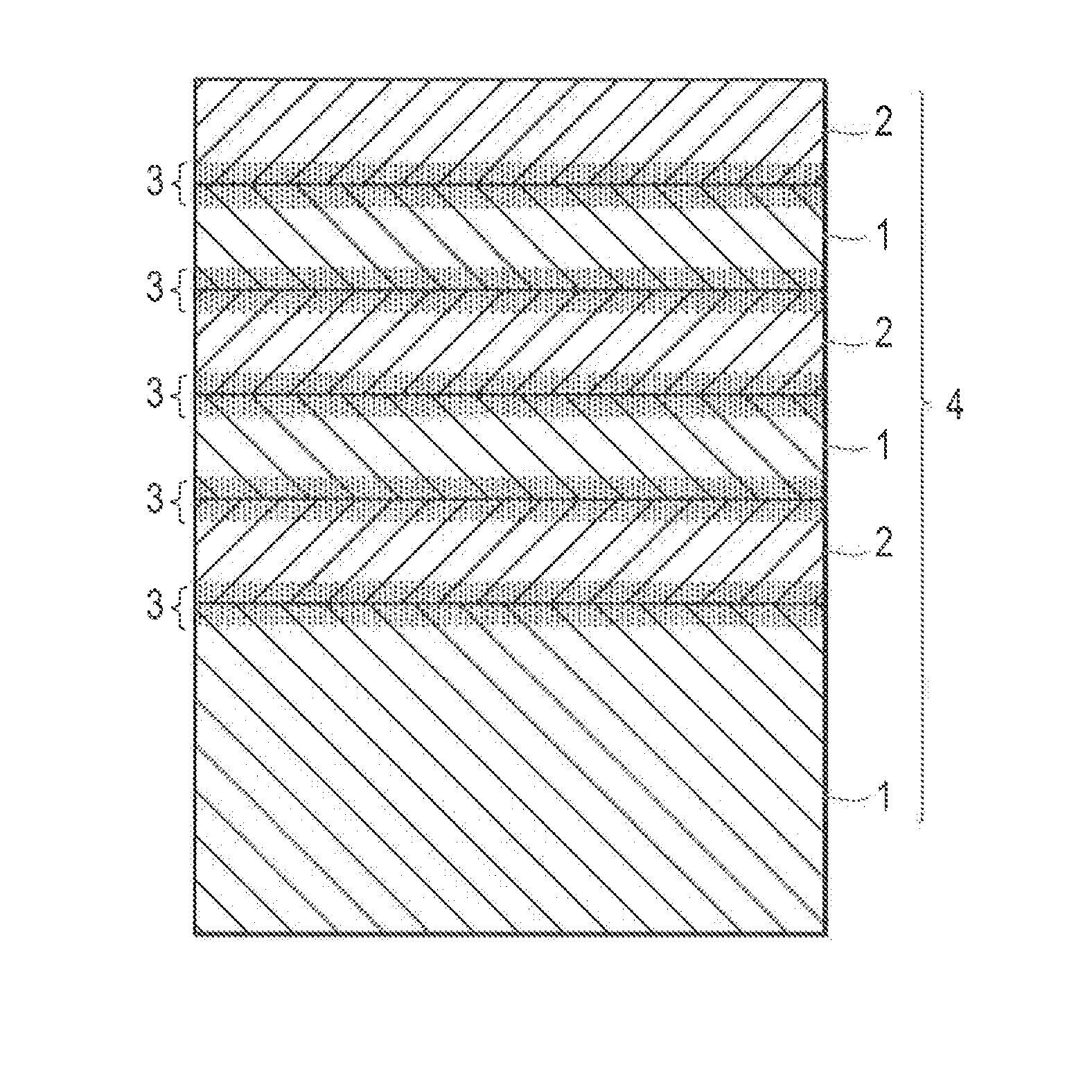
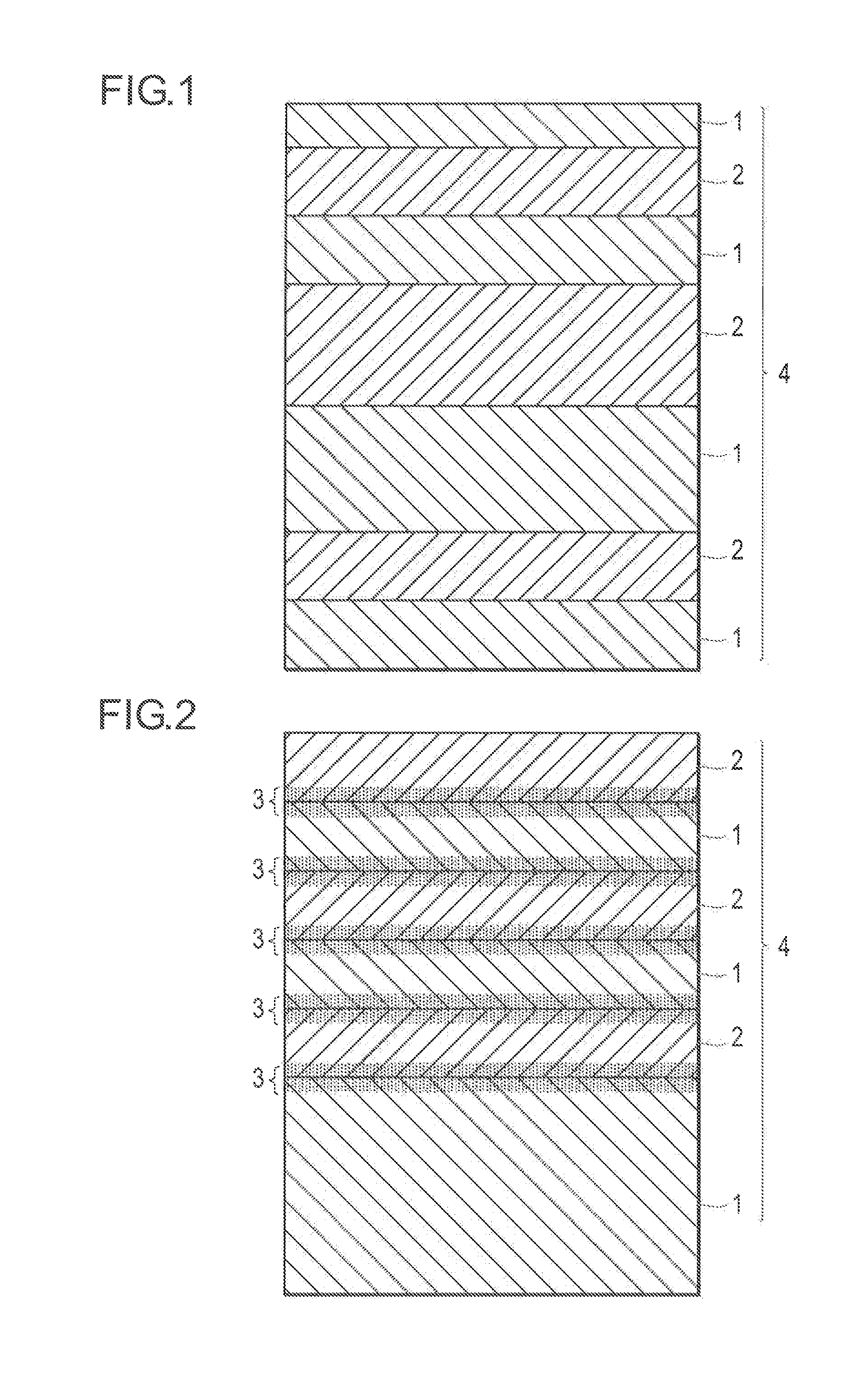
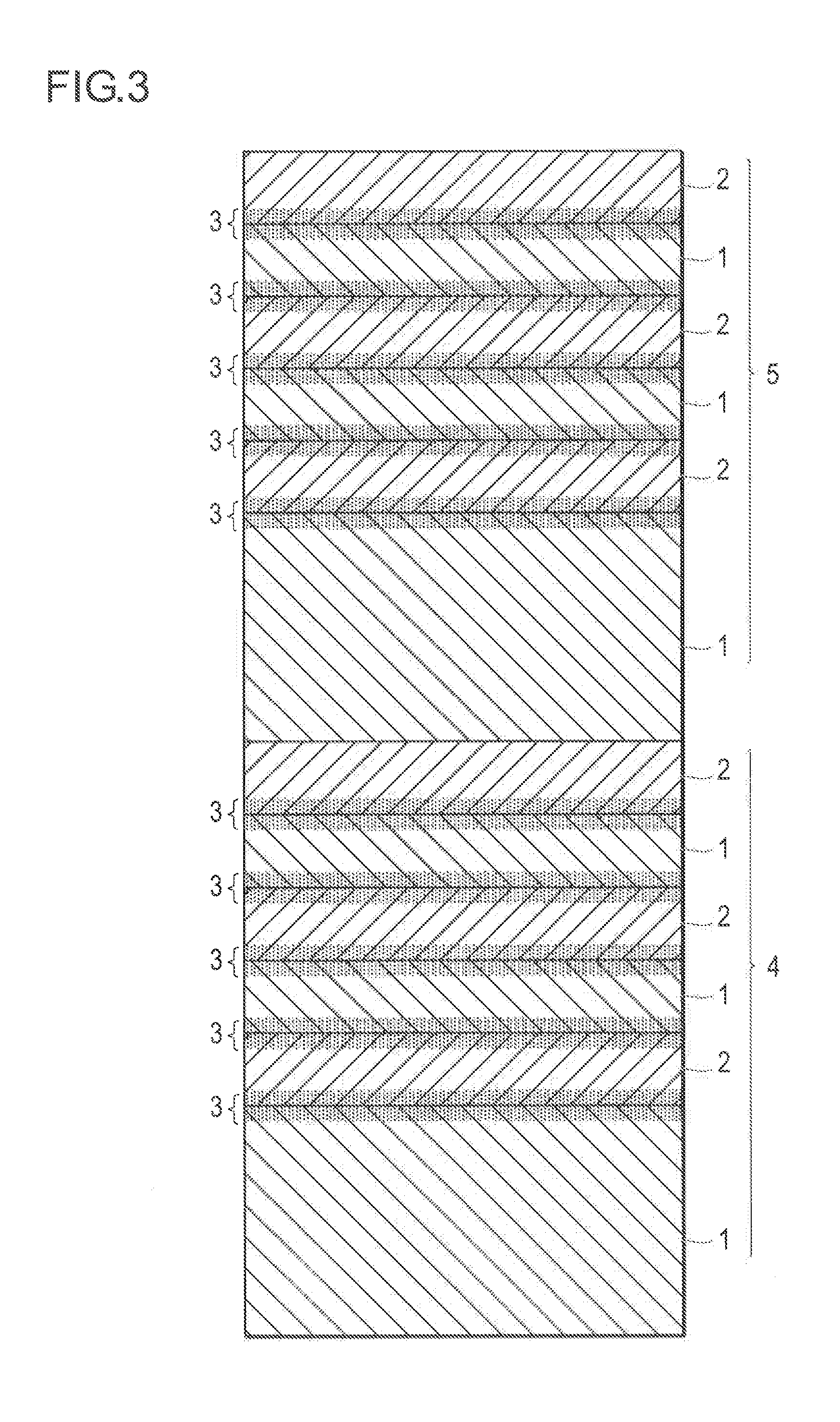
[Object]To provide a heat radiation reflective film which has a high heat radiation reflectance and good adherence property (peel resistance), which can have a large surface area, and which de-emphasizes certain visible reflected lights; and a method for producing the film. And to provide a heat radiation reflector which includes the heat radiation reflective film as described above.[Means of Realizing the Object]A heat radiation reflective film comprising: at least one heat radiation reflective unit on one surface of a support, the unit comprising: at least 6 laminated layers, each layer having a different refractive index from an adjacent layer, wherein a first unit as one of the heat radiation reflective units comprises the layer closest to the support having a thickness which is 3 times or more of the thickness of the layer farthest from the support.

Description

BACKGROUND[0001]1. Technical Field[0002]The present invention relates to a heat radiation reflective film and a method for producing the film, and a heat radiation reflector which includes the heat radiation reflective film.[0003]2. Description of Related Arts[0004]In recent years, a growing interest in energy conservation measures results in a growing demand for a heat radiation reflective film which blocks the transmission of solar heat through the window glass of a building and a vehicle to reduce the load on a cooling system.[0005]The spectrum of the solar light ranges from the ultraviolet to the infrared. Visible light, which corresponds to a color range of violet through yellow to red and a wavelength range of from 380 nm to 780 nm, occupies about 45% of the solar light. Infrared light occupies about 50% of the solar light. Infrared light includes the near-infrared light (wavelength range of from 780 nm to 2500 nm) near the visible region and the mid-infrared light in above th...

Claims


Application Information

Patent Timeline
IPC IPC(8): G02B5/08
CPCG02B5/0816G02B5/08G02B5/0808G02B5/085G02B5/281G02B5/282
Inventor NAKAJIMA, AKIHISA
Owner KONICA MINOLTA INC
Learn More