

Remote control system
a remote control and electric device technology, applied in the direction of electric controllers, ignition automatic control, instruments, etc., can solve the problems of increasing power consumption, difficult to reduce power consumption in standby mode, and increasing the amount of standby power consumed while the electric device is turned off, so as to reduce the leakage current flowing in the switching element and reduce power consumption.
- Summary
- Abstract
- Description
- Claims
- Application Information
AI Technical Summary
Benefits of technology
Problems solved by technology
Method used
Image

Examples
embodiment 1
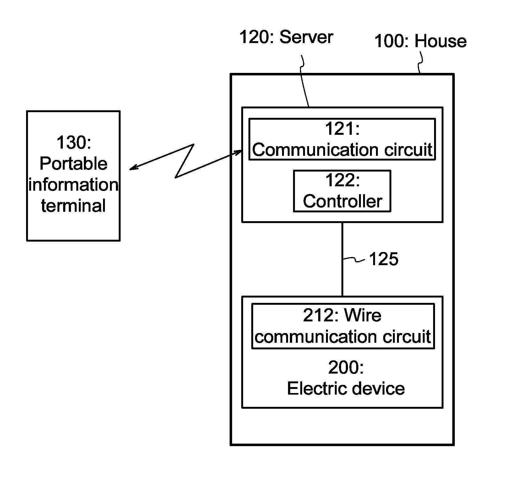
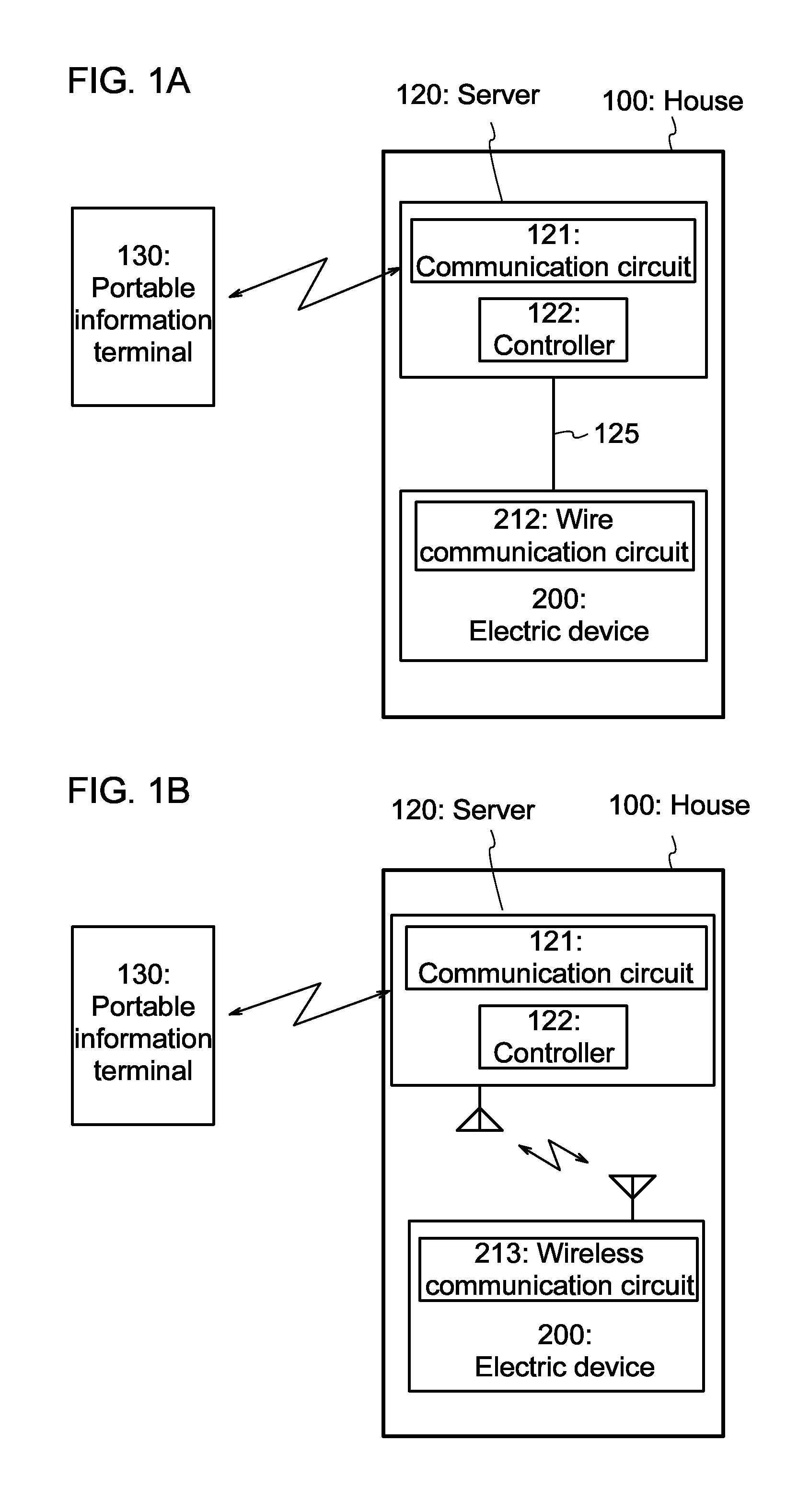
[0041]One embodiment of the present invention is described with reference to FIGS. 1A and 1B. A house 100 illustrated in FIG. 1A includes a server 120 and an electric device 200. The electric device 200 includes a wire communication circuit 212 and is connected to the server 120 through a wired LAN 125. The server 120 includes a communication circuit 121 and a controller 122. The communication circuit 121 transmits / receives information to / from a portable information terminal 130 through a telecommunication line such as a telephone line or an internet line. It is preferable that encrypted information be transmitted / received. The server 120 can control the operation of the electric device 200 by the controller 122 and can recognize operating information of the electric device 200. The portable information terminal 130 can remotely control the server 120 through the telecommunication line. This means that the portable information terminal 130 can remotely control the electric device 20...
embodiment 2
[0109]In this embodiment, specific examples of the electric device 200 are described with reference to FIG. 6 and FIG. 7. The house 100 illustrated in FIG. 6 includes a plurality of electric devices 200. In this embodiment, the electric devices 200 include a lighting device 101, an air conditioner 102, a telephone 103, a refrigerator 104, a microwave oven 105, a dishwasher 106, a washing machine 107, a computer 108, an audio equipment 109, a television 110, a self-propelled vacuum cleaner 111, a charging station 112, a bathroom 113, a bathroom controller 114, an imaging device 115, and a recording device 116.
[0110]The plurality of electric devices 200 are each provided with its own IP address and connected to the server 120 through the wired LAN 125. The server 120 has a function of communicating with the electric devices 200 through the wired LAN 125 to control the operation of each of the electric devices 200 and recognize operating information of each of the electric devices 200....
embodiment 3
[0130]In this embodiment, a structure of a transistor that is applicable to the power switches 151 and 152 disclosed in the above embodiments and a method for manufacturing the transistor will be described with reference to FIGS. 9A and 9B.
[0131]FIG. 9A is a top view of a transistor 300 that is applicable to the power switches 151 and 152. FIG. 9B is a cross-sectional view illustrating a stacked-layer structure taken along two-dot-dashed line A1-A2 in FIG. 9A. Note that in FIG. 9A, some components are omitted for easy understanding.
[0132]In the transistor 300 illustrated in FIGS. 9A and 9B, which is a power MOSFET, a semiconductor substrate 303 over a heat dissipation plate 301 is used as a back gate electrode, an insulating layer 302 is over the semiconductor substrate 303, a buffer layer 305 is over the insulating layer 302, and an oxide semiconductor layer 307 having a crystal structure is over the buffer layer 305. Note that the back gate electrode is positioned so that a channe...
PUM
 Abstract
Description
Claims
Application Information