

Arrays and methods for guided cell patterning
a cell patterning and array technology, applied in the field of arrays and methods for guided cell patterning, can solve the problems of cell death, prolonged viability of cells,
- Summary
- Abstract
- Description
- Claims
- Application Information
AI Technical Summary
Benefits of technology
Problems solved by technology
Method used
Image

Examples
example 1
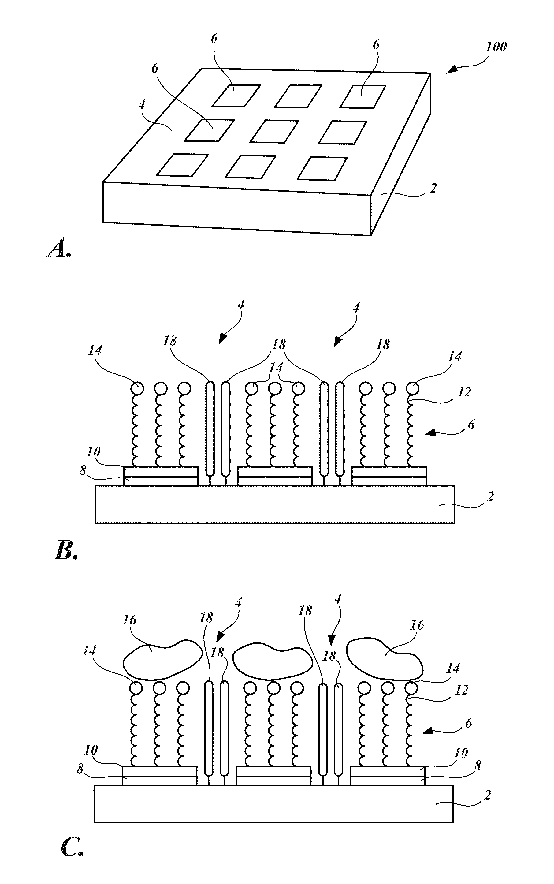
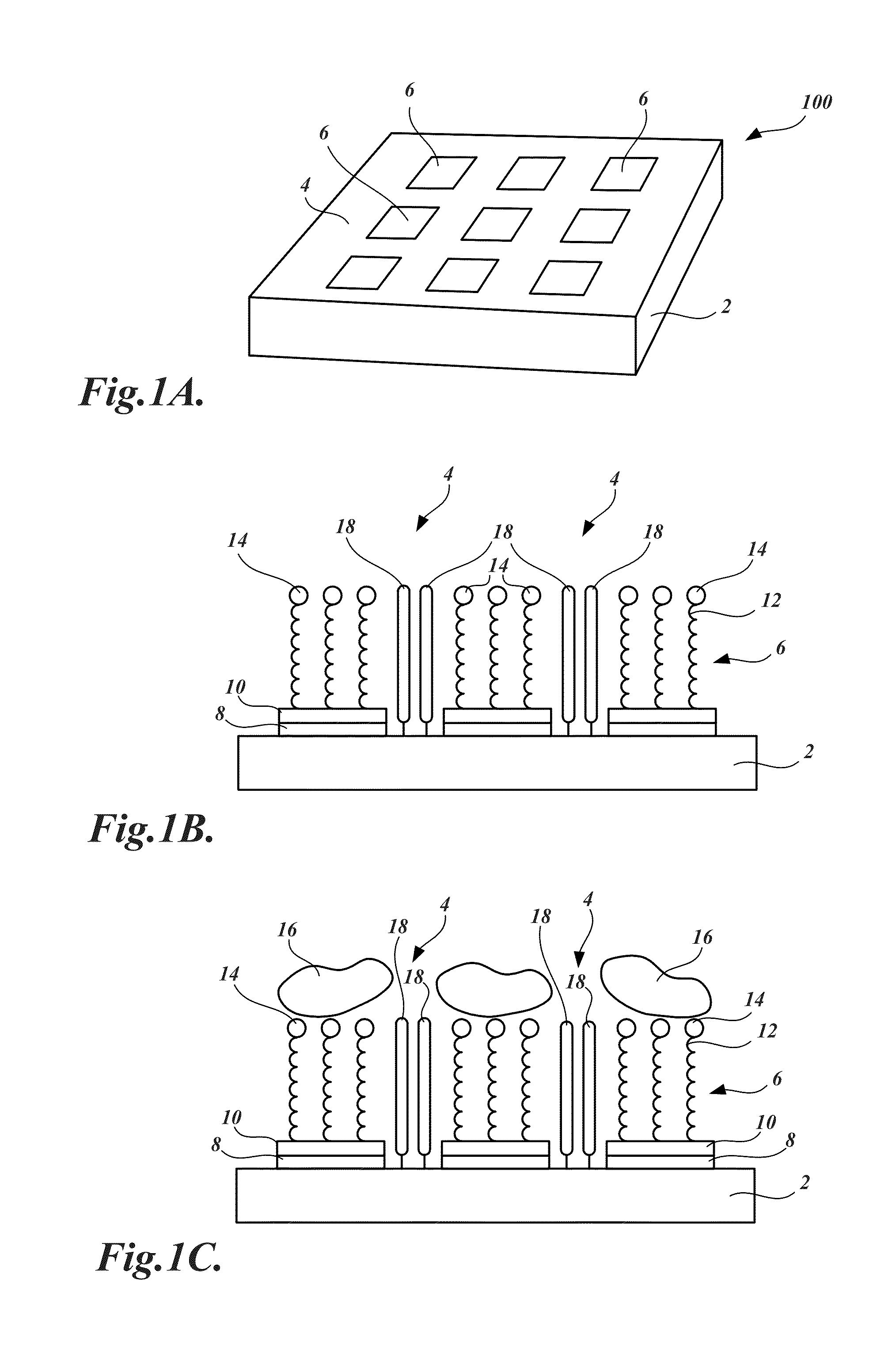
Representative Cell-Patterning Arrays with Cell-Adhesion Peptides Attached to Cell-Adhesion Sites
[0155]In this example, the preparation of a dry oxidized, native oxide depleted silicon surface useful in making representative cell-patterning array of the invention is described.
[0156]Substrate Preparation.
[0157]Four-inch p-type silicon substrates with (100) orientation were cleaned with piranha (hydrogen peroxide / sulfuric acid 2:5 v / v) at 120° C. for 10 minutes, dipped in HF, and rinsed with DI water thoroughly. A 1.1 μm layer of positive photoresist was then coated on the surface, and an array of 20 μm×20 μm gold squares (electrodes) spaced 60 μm apart was patterned on silicon oxide substrates by conventional microfabrication as follows. A 10 nm layer of titanium (Ti) was then deposited onto the photoresist-developed substrates at a deposition rate of 0.3 Å / s. A gold film of 100 nm in thickness was subsequently deposited onto the Ti at a deposition rate of 5 Å / s. The photoresist was ...
example 2
Detection of Bacterial Infection Using a Representative Cell-Patterning Array
[0168]In this example, a method for using a representative array of the invention for detecting bacterial infection is described.
[0169]Substrate Preparation.
[0170]Four inch p-type silicon substrates of (100) orientation were cleaned with piranha (hydrogen peroxide / sulfuric acid 2:5, v / v) at 120° C. for 10 minutes, dipped in HF, and thoroughly rinsed with DI water. A layer (1.1 μm) of positive photoresist was then coated on the surface, and patterns were formed on the substrate upon exposure to ultraviolet light through a mask with square patterns of three different sizes (25, 100, and 400 μm2). A titanium (Ti) layer (10 nm) was then deposited on the photoresist-developed substrates at a deposition rate of 0.3 Å / s. A gold film of 100 nm thickness was subsequently deposited on the Ti at a deposition rate of 5 Å / s. The photoresist was dissolved in acetone and the remaining metal film was lifted off. After lift...
example 3
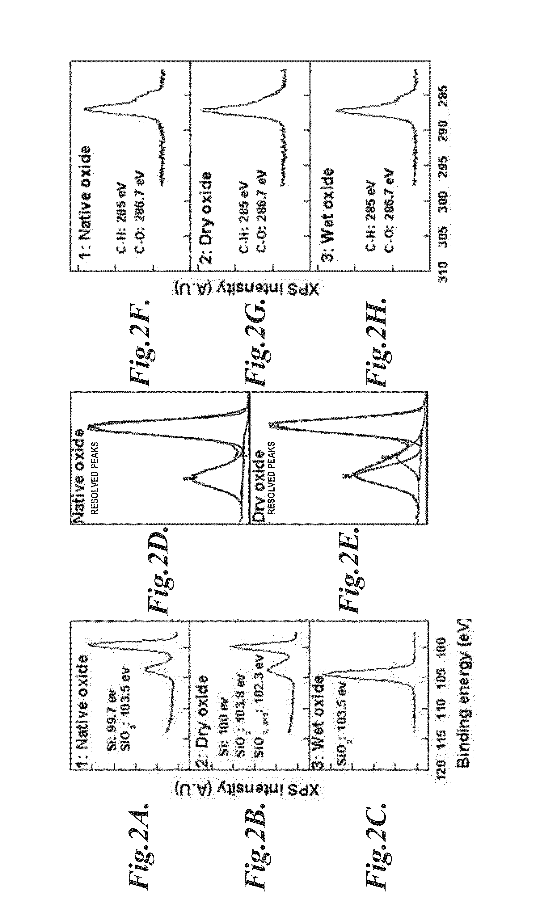
Comparison of Cell-Patterning Arrays Based on Native Silicon Surface, Wet Oxide Surface, and Dry Oxide Surfaces
[0182]In this example, the preparations of cell-patterning arrays based on native silicon surface, wet oxidized native oxide depleted silicon surface, and dry oxidized native oxide depleted silicon surface are described. The cellular viability and stability of these arrays are compared.
[0183]Substrate Preparation.
[0184]Four inch p-type silicon substrates of (100) orientation were cleaned with piranha (hydrogen peroxide / sulfuric acid 2:5 v / v) at 120° C. for 10 minutes, dipped in HF, and rinsed with DI water thoroughly. A layer of positive photoresist (1.1 μm) was then coated on the surface, and an array of squares (20 μm×20 μm) was patterned on the substrate upon exposure to UV light through a mask. A thin layer of titanium (Ti) of 10 nm in thickness was then deposited onto the photoresist-developed substrate at a deposition rate of 0.3 Å / s. Gold films of 100 nm in thickness...
PUM
| Property | Measurement | Unit |
|---|---|---|
| size | aaaaa | aaaaa |
| concentration | aaaaa | aaaaa |
| concentration | aaaaa | aaaaa |
Abstract
Description
Claims
Application Information