Organic electroluminescent device
a technology of electroluminescent devices and electroluminescent tubes, which is applied in the direction of thermoelectric devices, solid-state devices, organic chemistry, etc., can solve the problems of deteriorating efficiency, driving voltage or device life still not satisfactory, and unable to achieve luminous efficiency, etc., to achieve excellent hole and electron injection/transport properties, excellent stability and durability, and good balance
- Summary
- Abstract
- Description
- Claims
- Application Information
AI Technical Summary
Benefits of technology
Problems solved by technology
Method used
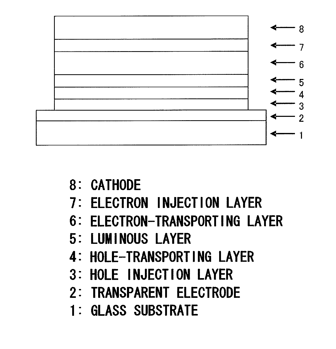
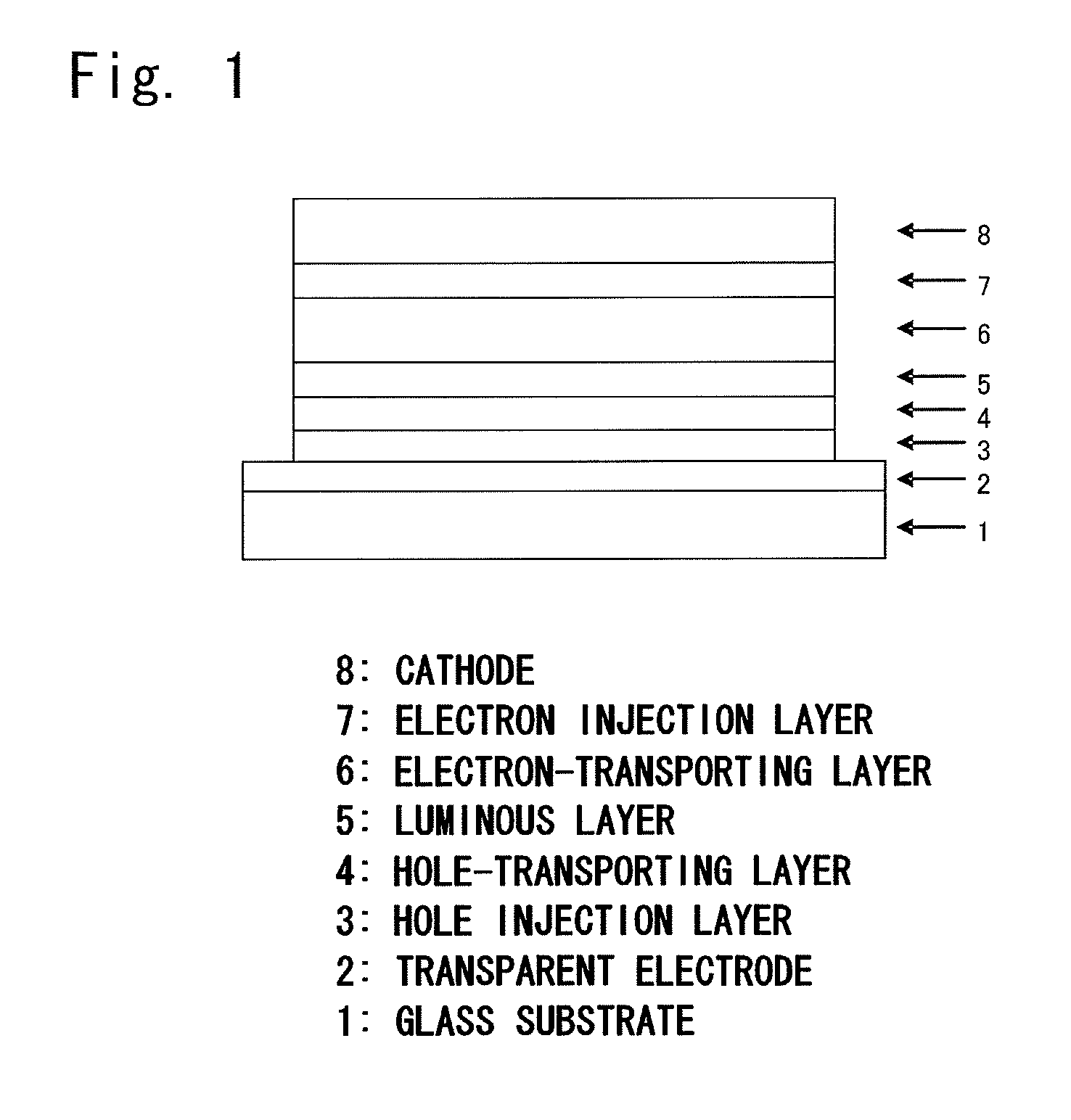
Image

Examples
example 1
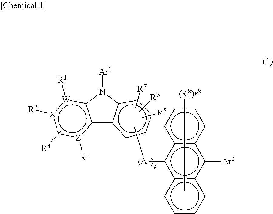
Synthesis of an 8-(9,10-diphenylanthracene-2-il)-5-phenyl-5H-pyrido[4,3-b]indole [compound (2-1)]
[0173]Into a reactor purged with nitrogen, there were added:
iodobenzene,43.0ml5H-pyrido[4,3-b]indole,50.0 gcopper powder,1.9 gpotassium carbonate,82.2gdimethyl sulfoxide,2.1ml
which were then heated at 170° C. and stirred for 3 hours. After cooled down to 100° C., 500 ml of toluene was added thereto, and the mixture was stirred at 100° C. for one hour. The insoluble matter was removed by filtration, and the filtrate was concentrated under reduced pressure to obtain a crude product.
[0174]The crude product was refined with a column chromatography (carrier: NH silica gel, eluent: toluene) to obtain 69.9 g of a yellow liquid of 5-phenyl-5H-pyrido[4,3-b]indol (yield, 96%).
Yellow liquid of the indole compound obtained above,27.2ganddimethylformamide,150 ml
were added into the reactor purged with nitrogen and to which was, further, added with stirring:
N-bromosuccinimide,23.8 g
and the mixture was ...
example 2
Synthesis of an 8-{9,10-di(naphthalene-2-il)-anthracene-2-il}-5-phenyl-5H-pyrido[4,3-b]indole [compound (2-2)]
[0179]By using the brominated product of the pyridoindole, i.e., (8-bromo-5-phenyl-5H-pyrido[4,3-b]indole obtained in Example 1, the compound was synthesized in a manner as described below.
[0180]Into the reactor purged with nitrogen, there were added:
the above brominated product of the pyridoindole,2.0g9,10-di(naphthalene-2-il)anthracene-2-boronic acid,3.5gtetrakis(triphenylphosphine)palladium,0.4 g2M potassium carbonate aqueous solution,10mltoluene,20 mlethanol,5 ml
and the mixture was heated and refluxed for 5.5 hours with stirring. After cooled down to room temperature, 50 ml of toluene and 30 ml of water were added thereto and the mixture was, thereafter, stirred, and the organic phase was separated. The organic phase was dehydrated with anhydrous magnesium sulfate and was concentrated under reduced pressure to obtain a crude product.
[0181]The crude product was refined wi...
example 3
Synthesis of an 8-{4-[10-(naphthalene-2-il)anthracene-9-il]phenyl}-5-phenyl-5H-pyrido[4,3-b]indole [compound (1-6)]
[0183]An 8-(4-bromophenyl)-5-phenyl-5H-pyrido[4,3-b]indole was synthesized, and this pyridoindole derivative was used as the starting material.
[0184]Into the reactor purged with nitrogen, there were added:
the above pyridoindole derivative,4.0 g10-(naphthalene-2-il)anthracene-9-boronic acid,4.1 gtetrakis(triphenylphosphine)palladium,0.3g2M potassium carbonate aqueous solution,15mltoluene,32mlethanol,8ml
and the mixture was heated and refluxed for 18 hours with stirring. After cooled down to room temperature, the precipitated product was collected by filtration. The precipitated product was dissolved in 1,2-dichlorobenzene while being heated, and the insoluble matter was removed by filtration. Thereafter, the filtrate was concentrated under reduced pressure to obtain a crude product.
[0185]The crude product was refined by recrystallization with 1,2-dichlorobenzene to obtain...
PUM
 Abstract
Description
Claims
Application Information
 - R&D
- Intellectual Property
- Life Sciences
- Materials
- Tech Scout
- Unparalleled Data Quality
- Higher Quality Content
- 60% Fewer Hallucinations
Browse by: Latest US Patents, China's latest patents, Technical Efficacy Thesaurus, Application Domain, Technology Topic, Popular Technical Reports.
© 2025 PatSnap. All rights reserved.Legal|Privacy policy|Modern Slavery Act Transparency Statement|Sitemap|About US| Contact US: help@patsnap.com