
Multiphase low lc buck regulator

a buck regulator, multi-phase technology, applied in the direction of power conversion systems, dc-dc conversion, instruments, etc., can solve the problems of significant power consumption, memory devices, and difficult to find space for large off-chip components, so as to reduce the size of inductor and capacitors, the effect of high efficiency

Active Publication Date: 2014-01-23
SANDISK TECH LLC
View PDF9 Cites 4 Cited by
  • Summary
  • Abstract
  • Description
  • Claims
  • Application Information

AI Technical Summary

Benefits of technology

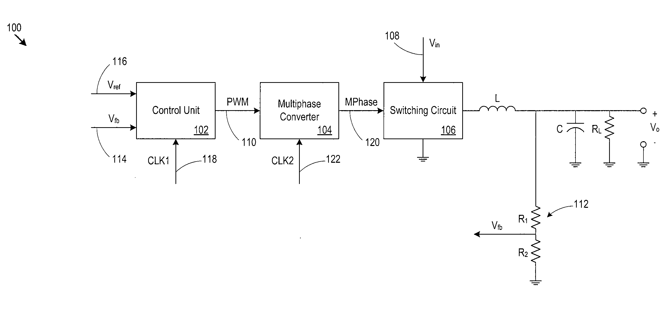
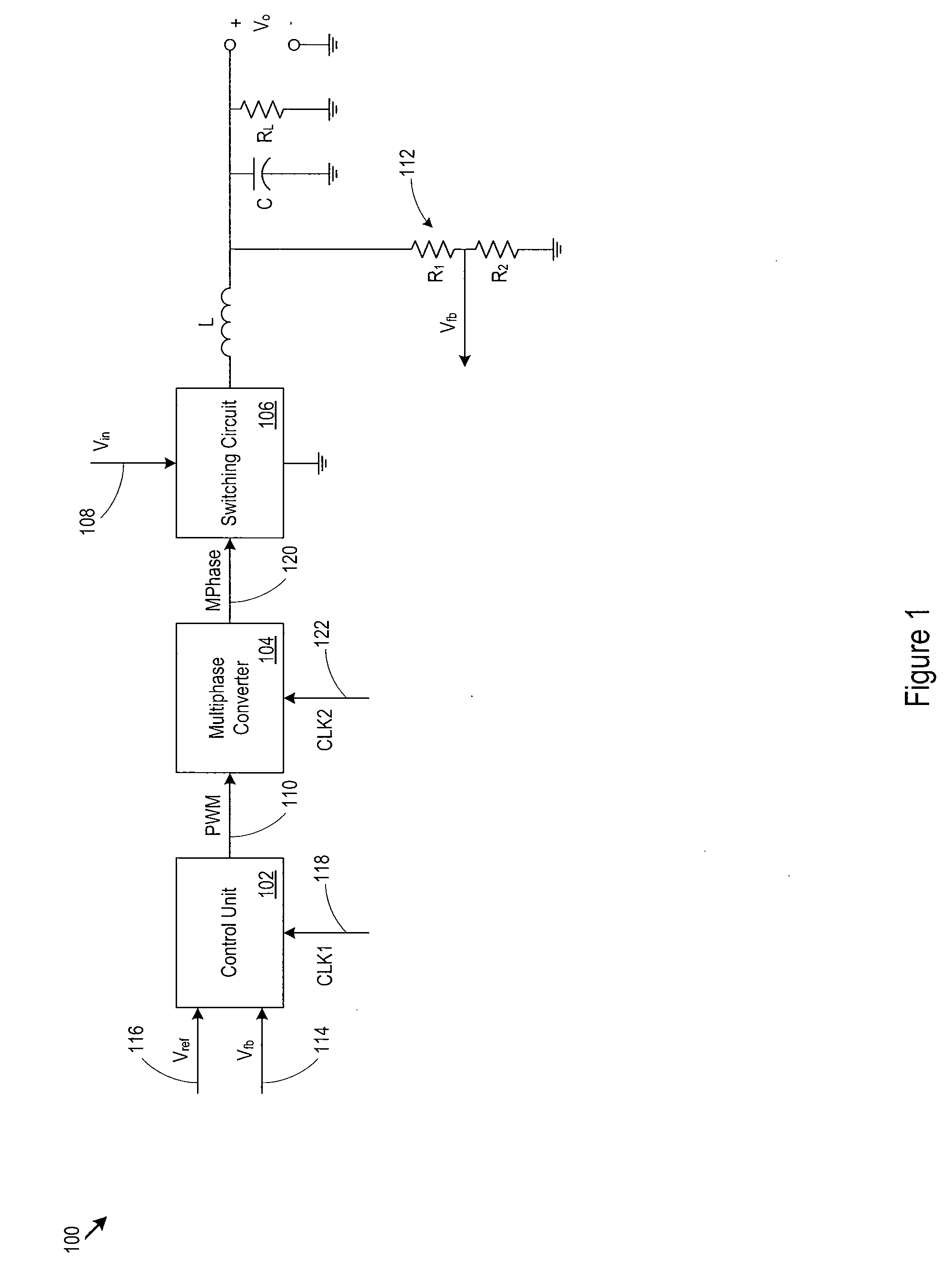
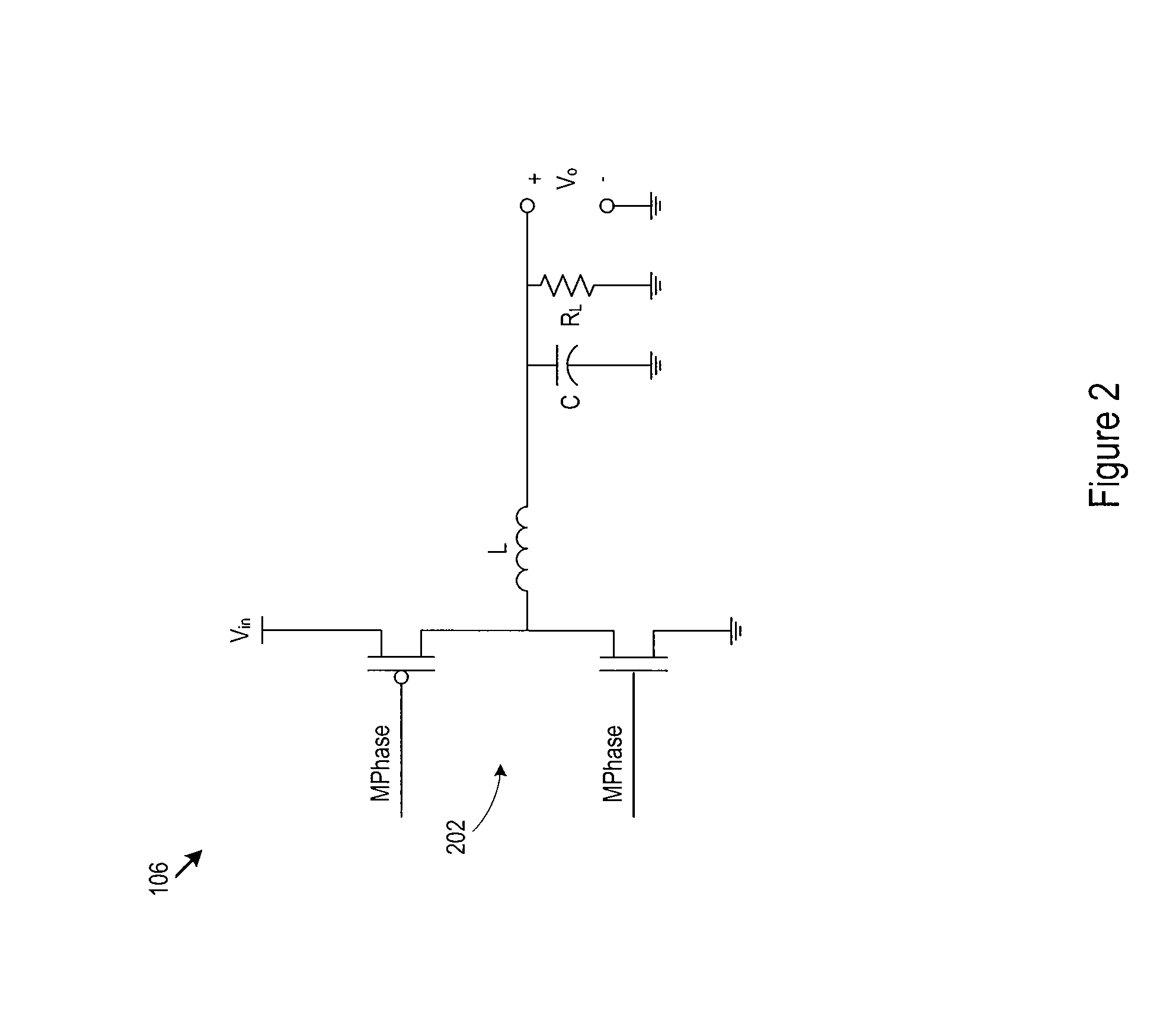
The buck power converter is a more efficient way to create a desired output voltage from a greater input voltage than traditional methods. It uses multiple integrated inductors and capacitors to achieve higher efficiency. A signal converter in the buck power converter determines the duty cycle of a switching control signal and outputs a modified multiphase signal to drive the power switching circuit. This reduces the size of the passive components and allows for integration onto chips or circuit boards. The output voltage ripple decreases with the number of phases in the modified signal, so the size of the components can be reduced by a factor.

Problems solved by technology

One important characteristic of a memory device is its power consumption.
However, memory devices present significant technical challenges to the use of a buck regulator.
As a result, it is difficult to find space for large off-chip components like the inductor or capacitor used in a buck regulator.
Furthermore, the components add extra cost to the memory device, and cost margins for memory devices are already very small.
Unfortunately, high switching frequencies increase design complexity and cost, while reducing the overall power efficiency.
This is often a difficult condition to meet, and commonly imposes significant restrictions on the maximum possible switching frequency.
As noted above, it is difficult and financially prohibitive to provide these extra components, particularly in a small, inexpensive memory device.

Method used


Image

  • Multiphase low lc buck regulator
  • Multiphase low lc buck regulator
  • Multiphase low lc buck regulator

Examples


Embodiment Construction

[0022]The discussion below makes reference to host devices and memory devices. A host device may be a wired or wireless device, may be portable or relatively stationary, and may run from DC (e.g., battery power), AC power, or another power source. A host device may be a consumer electronic device such as a personal computer, a mobile phone handset, a game device, a personal digital assistant (PDA), an email / text messaging device, a digital camera, a digital media / content player, a GPS navigation device, a satellite signal (e.g., television signal) receiver, or cable signal (e.g., television signal) receiver. In some cases, a host device accepts or interfaces to a memory device that includes the power converter. Examples of memory devices include memory cards, flash drives, and solid state disk drives. For example, a music / video player may accept a memory card that incorporates the power converter described below, or a personal computer may interface to a solid state disk drive that ...


PUM


Abstract

A buck power converter creates a desired output voltage from a greater input voltage with higher efficiency than linear regulators or charge pumps. For compact-size and cost sensitive products, the use of the buck power converter is hindered mainly because of lack of physical space and increases in the cost of the passive components like the inductor and capacitor. Techniques are presented to reduce the sizes of the passive components so that they can be integrated on-chip or in-package or on board. A signal converter in the buck power converter determines the duty cycle of a switching control signal. The switching control signal would ordinarily have driven a power switching circuit that provides current to the inductor in the buck power converter. The signal converter outputs a modified (multiphase) switching control signal that includes multiple separated on-periods that taken together approximate the duty cycle of the switching control signal while maintaining the same control loop frequency. The multiphase switching signal drives the power switching circuit to provide current to the inductor during each of the multiple separated on-periods so that the output voltage ripple decreases by a factor of the number of phases in the modified switching signal. In this way, if the ripple amplitude is kept same, the sizes of the passive components can be reduced by the factor of the number of phases in the modified switching control signal.

Description

BACKGROUND OF THE INVENTION[0001]1. Technical Field[0002]This disclosure relates to power converters. In particular, this disclosure relates to a step down (buck) power converter with inductor based switching, suitable for use with a memory device (e.g., a flash memory device) or other device.[0003]2. Related Art[0004]Continual development and rapid improvement in semiconductor manufacturing techniques have led to extremely high density memory devices. The memory devices are available in a wide range of types, speeds, and functionality. Memory devices often take the forms, as examples, of flash memory cards and flash memory drives. Today, capacities for memory devices have reached 64 gigabytes or more for portable memory devices such as Universal Serial Bus (USB) flash drives, and one terabyte or more for solid state disk drives. Memory devices form a critical part of the data storage subsystem for digital cameras, digital media players, home computers, and an entire range of other ...

Claims


Application Information

Patent Timeline
IPC IPC(8): H02M1/08
CPCH02M1/08H02M3/1584
Inventor PANCHOLI, DEEPAKODEDARA, BHAVIN
Owner SANDISK TECH LLC
Learn More