
Method and system for active-illumination parallel raman microspectroscopy

Active Publication Date: 2014-01-30
UNIV HOUSTON SYST
View PDF9 Cites 8 Cited by
  • Summary
  • Abstract
  • Description
  • Claims
  • Application Information

AI Technical Summary

Benefits of technology

The described system uses a special optical component called a spatial light modulator to create a pattern of laser light that can be focused onto multiple points simultaneously. This allows for more flexible and efficient imaging. Combining this with wide-field Raman imaging technology allows for even more flexibility and efficient-side imaging. The system has high laser power and doesn't require any scanning. This makes it easier to gather information from multiple points and reduces the time needed for imaging.

Problems solved by technology

However, conventional laser scanning confocal Raman microscopy requires long data acquisition time due to its sequential operation, as well as the additional latency from the readout time of low-noise charge coupled device (CCD) detectors.
As a result, conventional point-scan Raman mapping is a time-consuming process and, for example, can take as long as a few hours to map a 50×50 μm2 region.
Although EMCCD can effectively overcome the read noise due to the short integration time per point measurement (˜msec), substantial noise is generated during the multiplication process.
In addition, the throughput advantage can be severely undermined for common specimens, where the Raman scattering cross section is typically small, and thus requires much longer integration time to achieve a decent signal-to-noise ratio.
Although efficient, the line-scan approach suffers from a major limitation: parallelism is only possible for points lying on a line, which severely undermines its throughput advantage when sparse sampling is desired.

Method used


Image

  • Method and system for active-illumination parallel raman microspectroscopy
  • Method and system for active-illumination parallel raman microspectroscopy
  • Method and system for active-illumination parallel raman microspectroscopy

Examples


example 1

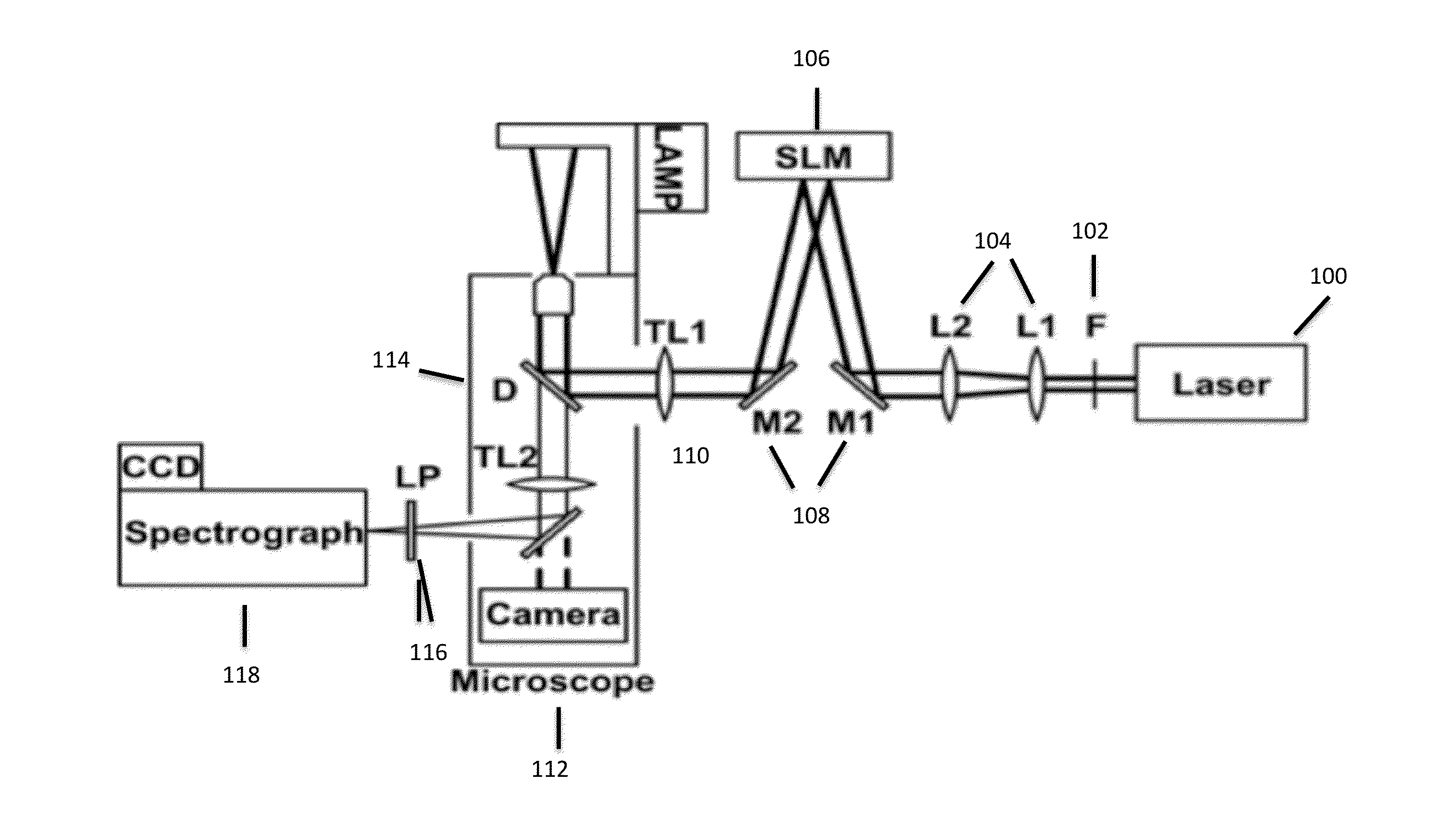
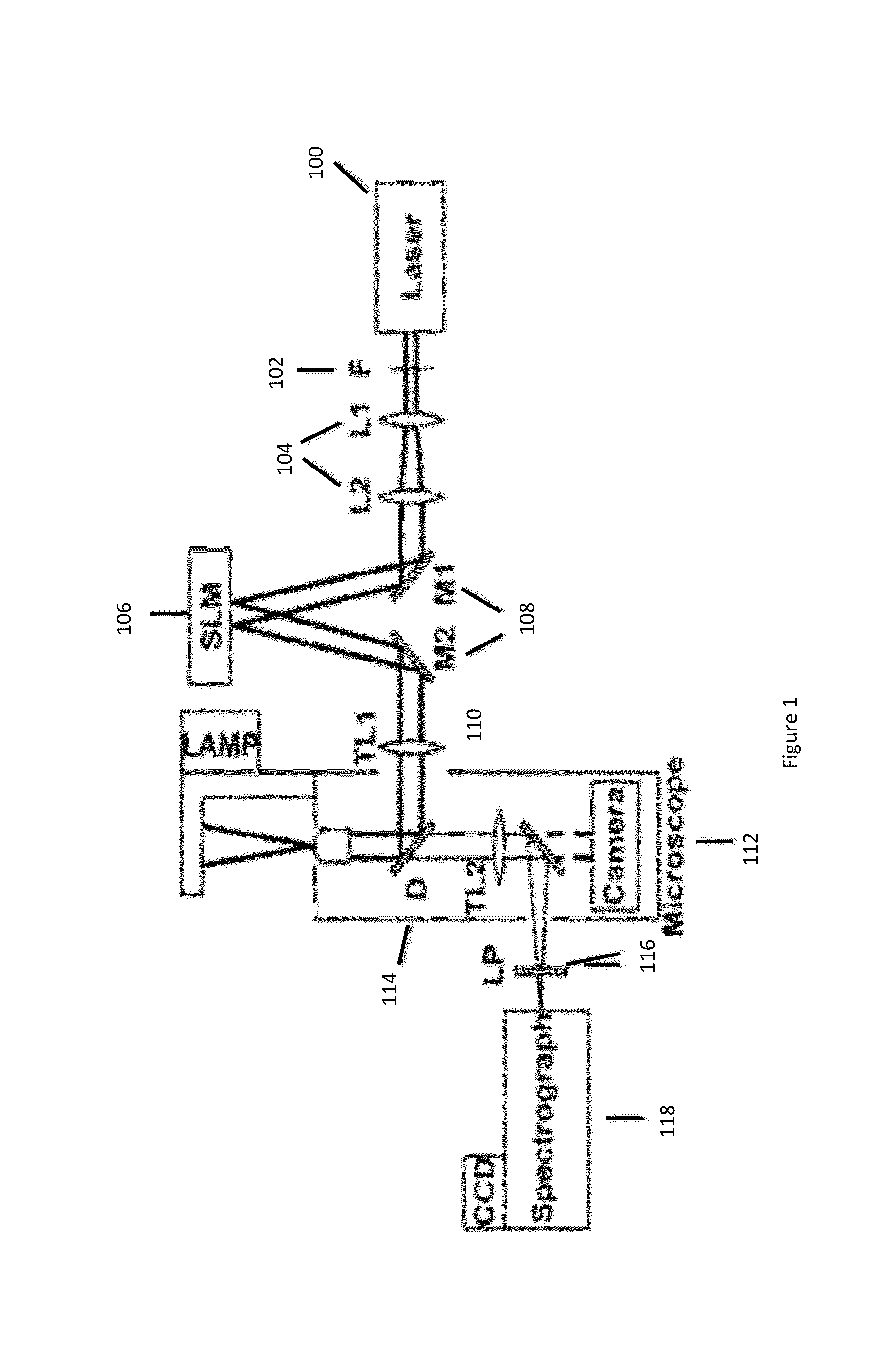
[0029]The system configuration is shown in FIG. 1. The 785 nm output of a CW Titanium:Sapphire laser (Spectra-Physics 3900S) was filtered by a laser-line filter (Semrock LL01-785-12.5) and expanded to ˜1 cm in diameter before the spatial light modulator (SLM, LCOS Hamamatsu). The output from the SLM was fed through the back port of an inverted microscope (Olympus IX71) with an addition of a tube lens. A dichroic mirror (Semrock LPD01-785RU-25) was placed in the microscope turret for epi-Raman acquisition via a microscope objective (Olympus UPLSAPO 60XW, 1.2 NA). The Raman light was redirected out via the microscope side port, filtered by a long-wave pass filter (Semrock LP02-785RS-25), and sent into a spectrograph (Acton 300i) with a thermal-electrically cooled CCD camera (Princeton 400BR-excelon). Developed code was used to program the SLM to generate illumination patterns. The CCD data acquisition and the SLM pattern generation were synchronized by Labview (National Instrument).

[0...


PUM


Abstract

An active-illumination parallel Raman microspectroscopy scheme for simultaneously collecting Raman spectra from multiple points in a full-spectra range. A combination of multi-point laser illumination with wide-field Raman imaging is employed in order to allow for simultaneous imaging of multiple points not aligned on a single line.

Description

RELATED APPLICATIONS [0001]This application claims priority to U.S. Provisional Patent Application Ser. No. 61 / 585,927, filed Jan. 12, 2012, which is hereby incorporated by reference for all purposes.FIELD OF THE INVENTION [0002]Embodiments of the present invention relate to a method and process for exciting Raman scattering from a sample and simultaneously colleting Raman spectra from multiple points.BACKGROUND [0003]Generally speaking, Raman spectroscopy can provide molecular information via inelastic light scattering without physical contact. Coupled with microscopic imaging, Raman spectroscopy is a powerful technique for compositional analysis via inelastic light scattering. Raman microspectroscopy can be utilized for material analysis in many different ways that can include, for example, stress and temperature measurement in silicon and compositional analysis of polymer microparticles. Raman spectroscopy is particularly useful in obtaining microscopic information over a sizable...

Claims


Application Information

Patent Timeline
IPC IPC(8): G01J3/44
CPCG01J3/44G01J3/0229
Inventor SHIH, WEI-CHUAN
Owner UNIV HOUSTON SYST
Learn More