
Nanofiber scaffolds for biological structures

Active Publication Date: 2014-01-30
NFS IP HLDG LLC
View PDF2 Cites 35 Cited by
  • Summary
  • Abstract
  • Description
  • Claims
  • Application Information

AI Technical Summary

Benefits of technology

The present invention provides a synthetic construct that can be transplantated into a biological organism for the purpose of replacing or repairing damaged tissues. This construct consists of a two-dimensional or three-dimensional polymer scaffold, which is shaped and dimensioned based on the structure of a native biological structure, and which includes at least one layer of polymer fibers deposited by electrospinning. Additionally, the polymer scaffold can be preseeded with biological cells prior to implantation into the organism to facilitate integration with the organism and to enable the scaffold to function in a similar manner to the native structure. The invention also provides a system for manufacturing the synthetic construct and a variety of biological cells that can be used for preseeding the scaffold.

Problems solved by technology

Current methods of electrospinning aligned fibers are not known to achieve the ideal alignment of fibers observed in the human body, such as, for example, in brain tissue.

Method used


Image

  • Nanofiber scaffolds for biological structures
  • Nanofiber scaffolds for biological structures
  • Nanofiber scaffolds for biological structures

Examples


example 1

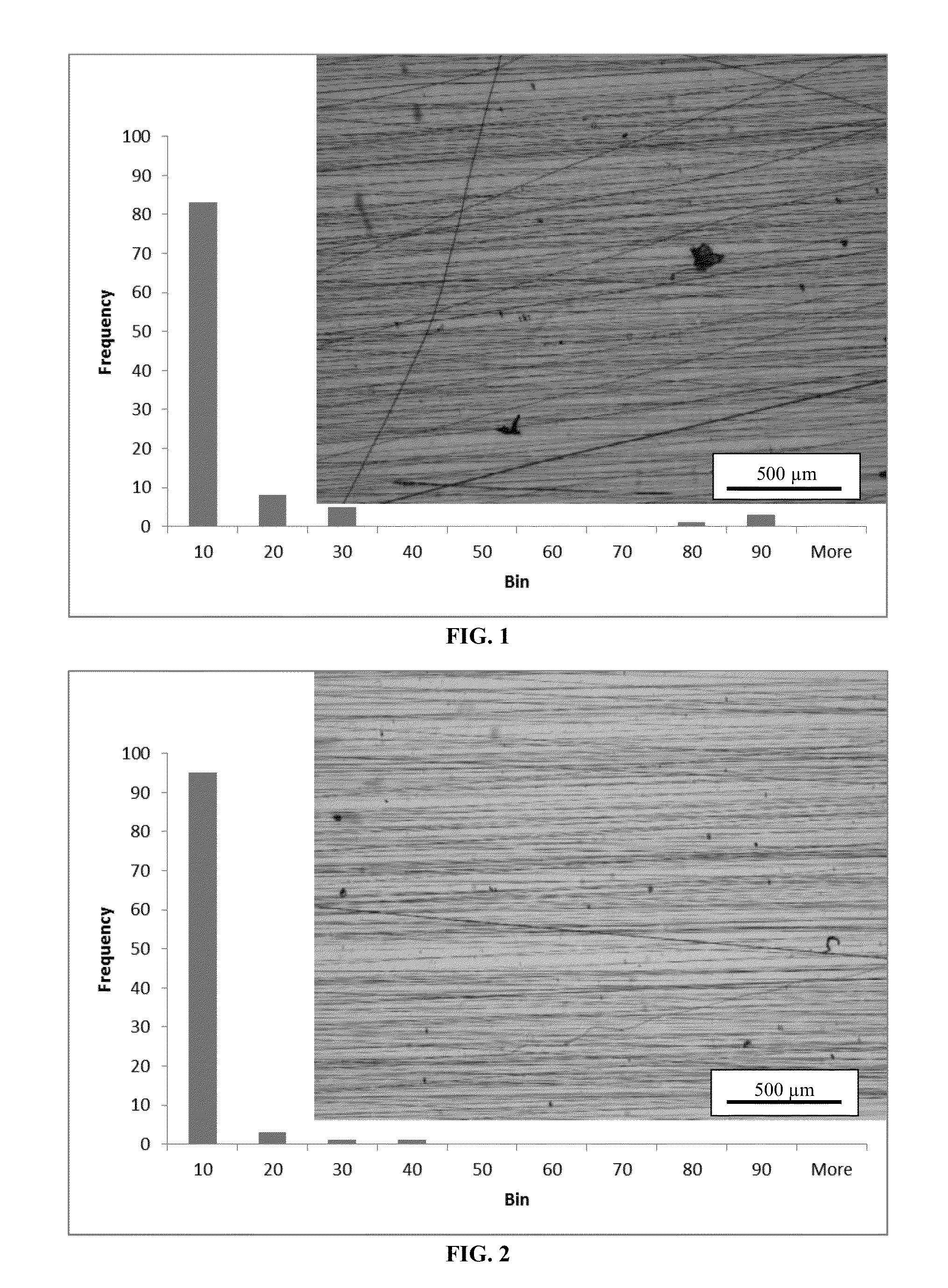
[0038]In Example 1, patch material was formed by fiber spinning the precursor solution at a deposition rate of 1 ml / h at a tip to substrate distance of 20 cm, while rotating the surface at a rate of 478 RPM (15.7 m / s) for a period of 2 hours, using a + / −4.2 kV field. The resulting fibers had an alignment of about 91% (that is, 91% of the fibers had a fiber angle within 10° from the spinning direction of the wheel).

example 2

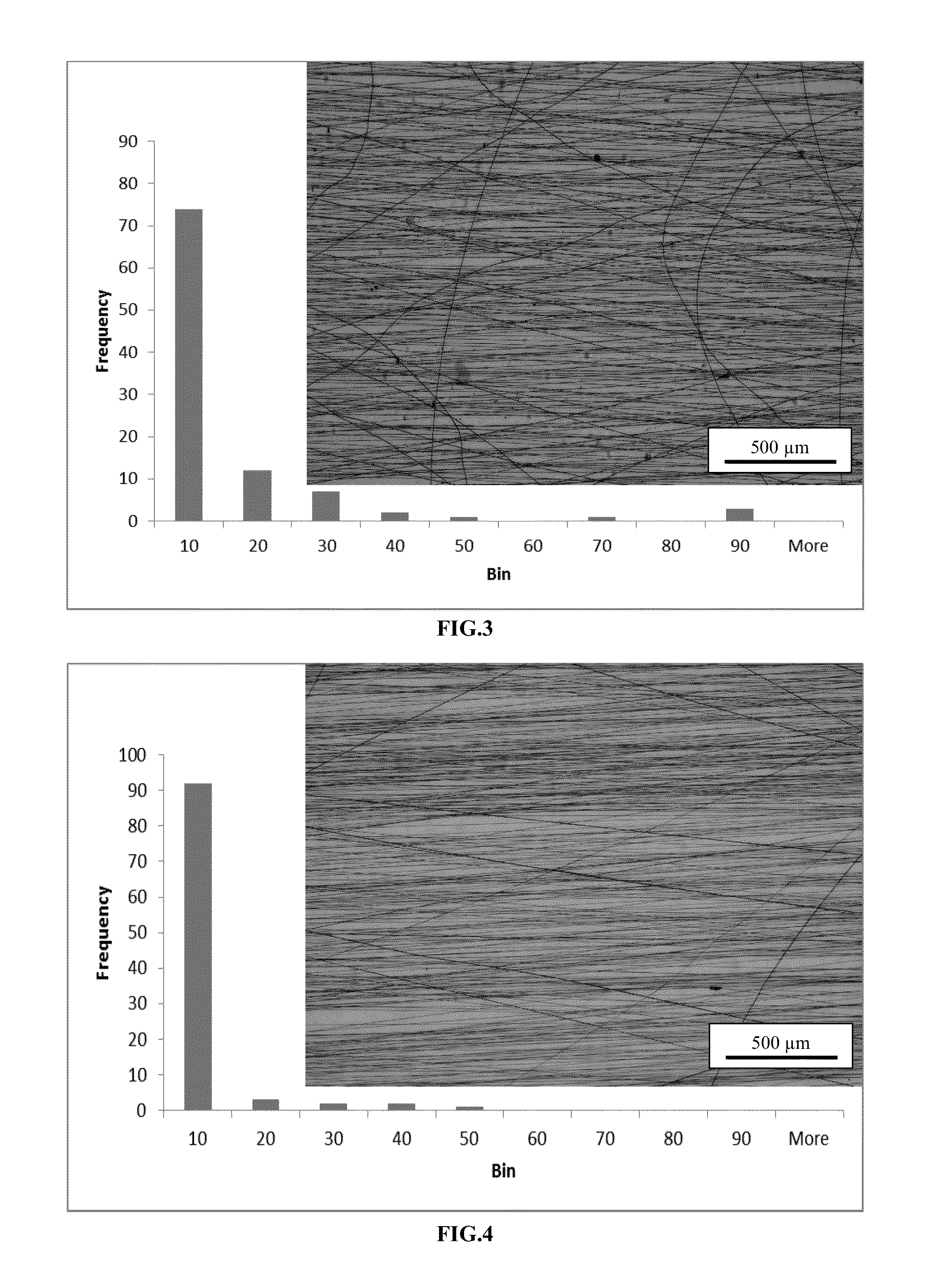
[0039]In Example 2, patch material was formed by fiber spinning the precursor solution at a deposition rate of 1 ml / h at a tip to substrate distance of 20 cm, while rotating the surface at a rate of 478 RPM (15.7 m / s) for a period of 2 hours, using a + / −5.0 kV field. The resulting fibers had an alignment of about 75%.

example 3

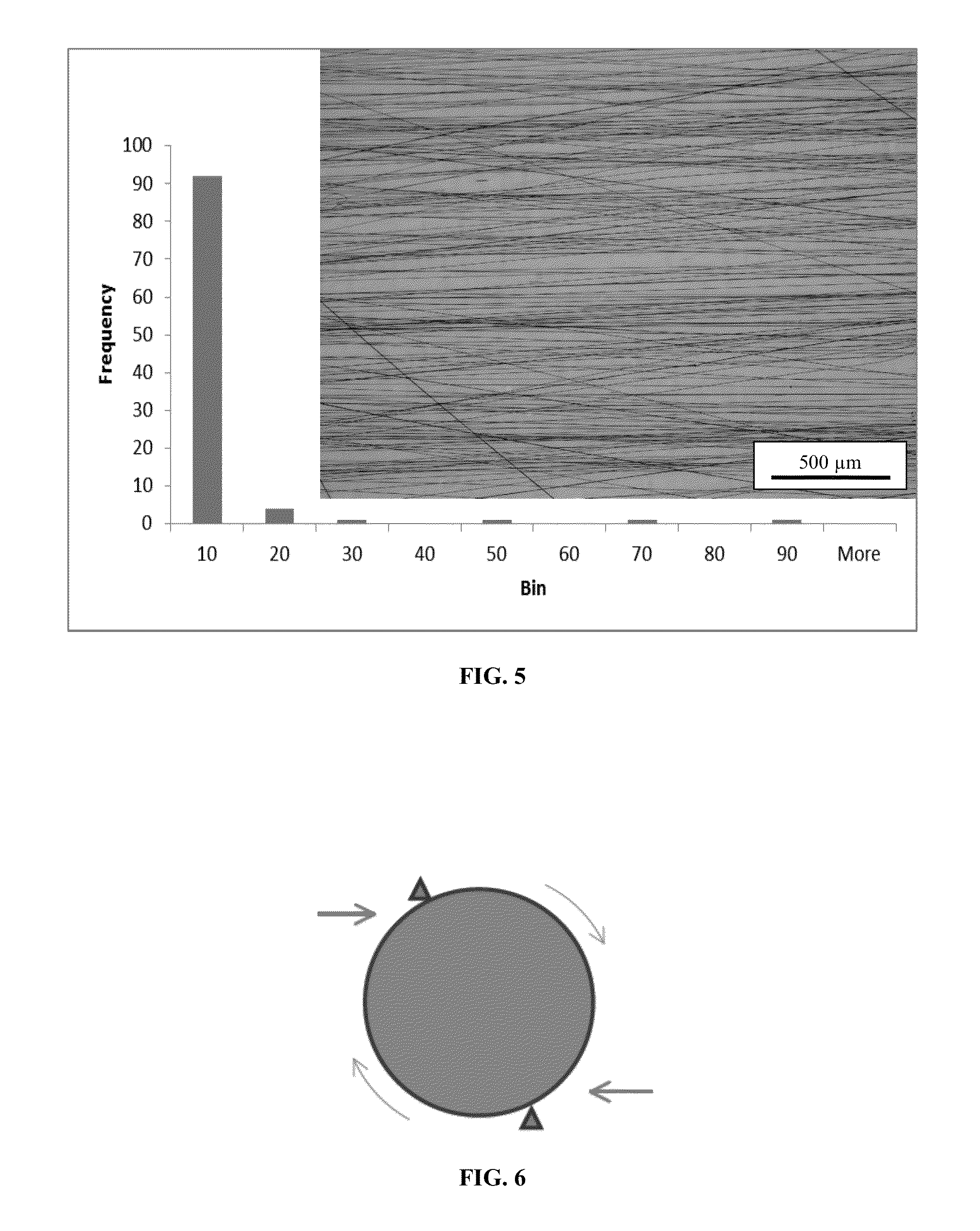
[0040]In Example 3, patch material was formed by fiber spinning the precursor solution at a deposition rate of 1 ml / h at a tip to substrate distance of 20 cm, while rotating the surface at a rate of 478 RPM (15.7 m / s) for a period of 2 hours, using a + / −4.8 kV field. The resulting fibers had an alignment of about 98%.

[0041]In this embodiment, to speed the growth of human tissue into the fiber preform, the fibers were aligned by rapidly spinning the preform so that alignment of the structure produced by standard electrospinning while the fibers were drawn into a substantially parallel ordering by the tension created by spinning the form. The properties of the fibers can be controlled to optimize the fiber diameter, the fiber spacing or porosity, the morphology of each fiber such as the porosity of the fibers or the aspect ratio, varying the shape from round to ribbon-like. The precursor solution may be controlled to optimize the modulus or other mechanical properties of each fiber, t...


PUM

PropertyMeasurementUnit
Fractionaaaaaaaaaa
Fractionaaaaaaaaaa
Fractionaaaaaaaaaa

Abstract

A system for manufacturing an artificial construct suitable for transplantation into a biological organism that includes a two or three three-dimensional preform that is based on the actual two or three-dimensional structure of a native mammalian tissue; and an electrospinning apparatus, wherein the electrospinning apparatus is operative to deposit at least one layer of polymer fibers on the preform to form a polymer scaffold, and wherein the orientation of the fibers in the scaffold relative to one another is substantially parallel.

Description

CROSS-REFERENCE TO RELATED APPLICATIONS[0001]This patent application claims the benefit of U.S. Provisional Patent Application Ser. No. 61 / 585,869 filed on Jan. 12, 2012, and entitled “Biocompatible Nanofiber Materials for Biological Structures,” the disclosure of which is hereby incorporated by reference herein in its entirety and made part of the present U.S. utility patent application for all purposes.BACKGROUND OF THE INVENTION[0002]Tissue engineering involves the synthesis of biologically relevant tissue for a wide range of applications including wound healing and the replacement or support of damaged organs. A common strategy is culturing target specific cells in vitro in a scaffold followed by implantation of the scaffold in a biological organism. As a logical cellular source for tissue engineering, stem cells have attracted a great deal of attention due to their relatively fast proliferation rate and diverse differentiation potential to various phenotypes. These include cell...

Claims


Application Information

Patent Timeline
IPC IPC(8): A61K9/70A61K47/32A61K35/12
CPCA61K9/70A61K47/32A61K35/12A61L27/3804A61L27/54A61L27/60A61L2300/252A61L2300/406A61L2300/41A61L2300/414
Inventor JOHNSON, JED K.
Owner NFS IP HLDG LLC
Learn More