Dielectric resonator array antenna

a technology of dielectric resonator array and array antenna, which is applied in the direction of antennas, leaky waveguide antennas, electrically short antennas, etc., can solve the problems of complex configuration of feeding circuit, method cannot be used in an application field requiring beam forming or beam scanning,

Inactive Publication Date: 2014-02-13
SAMSUNG ELECTRO MECHANICS CO LTD +1
View PDF6 Cites 257 Cited by
  • Summary
  • Abstract
  • Description
  • Claims
  • Application Information

AI Technical Summary

Benefits of technology

[0035]The dielectric resonator array antenna may further include a power source IC configured to include one or more power supply units which individually supply first high frequency signals to the one or more series-feed type array elements or combine the first high frequency signals to simultaneously supply them.
[0036]The power source IC...

Problems solved by technology

However, the method for feeding the related art patch array antenna is disadvantageous in that a beam pattern is fixed because a phase of an input signal transferred to an individual antenna element is not adjusted, and thus, the method cannot be used in an application field requiring beam forming or beam scanning.
Also, in case that a beam pattern of the related art patch array antenna is intended to be deformed, an individu...

Method used


Image

  • Dielectric resonator array antenna
  • Dielectric resonator array antenna
  • Dielectric resonator array antenna

Examples


Embodiment Construction

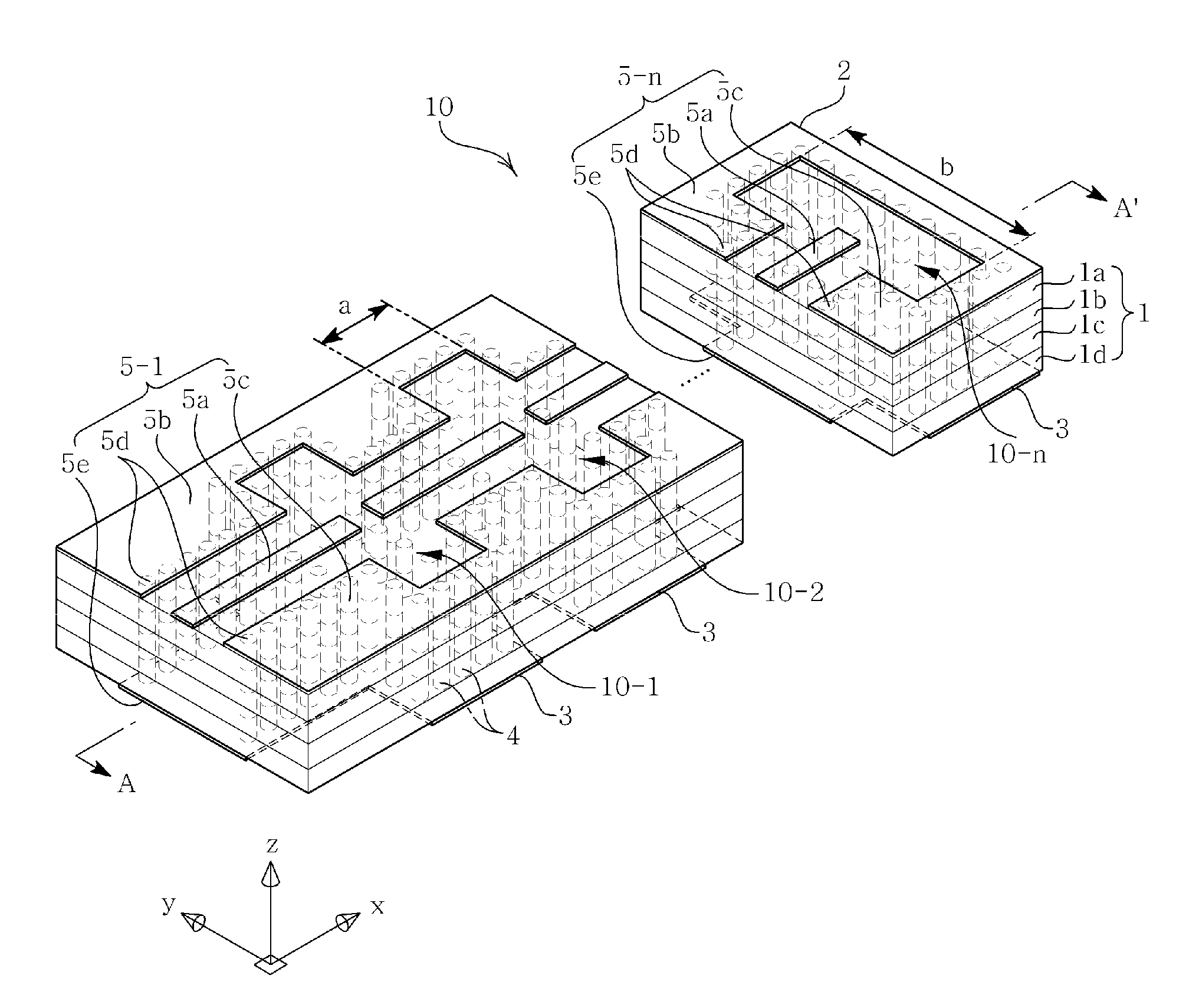
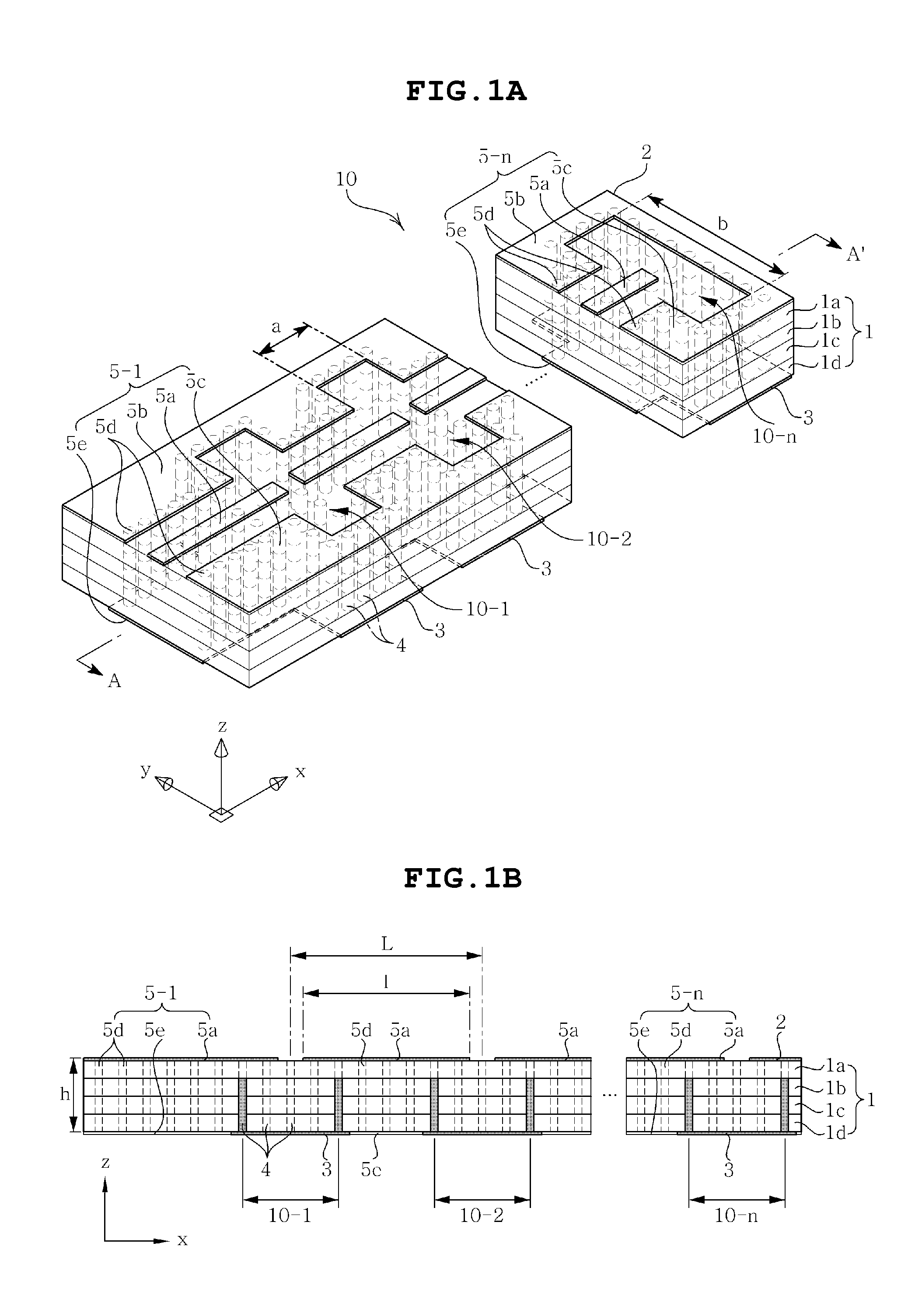
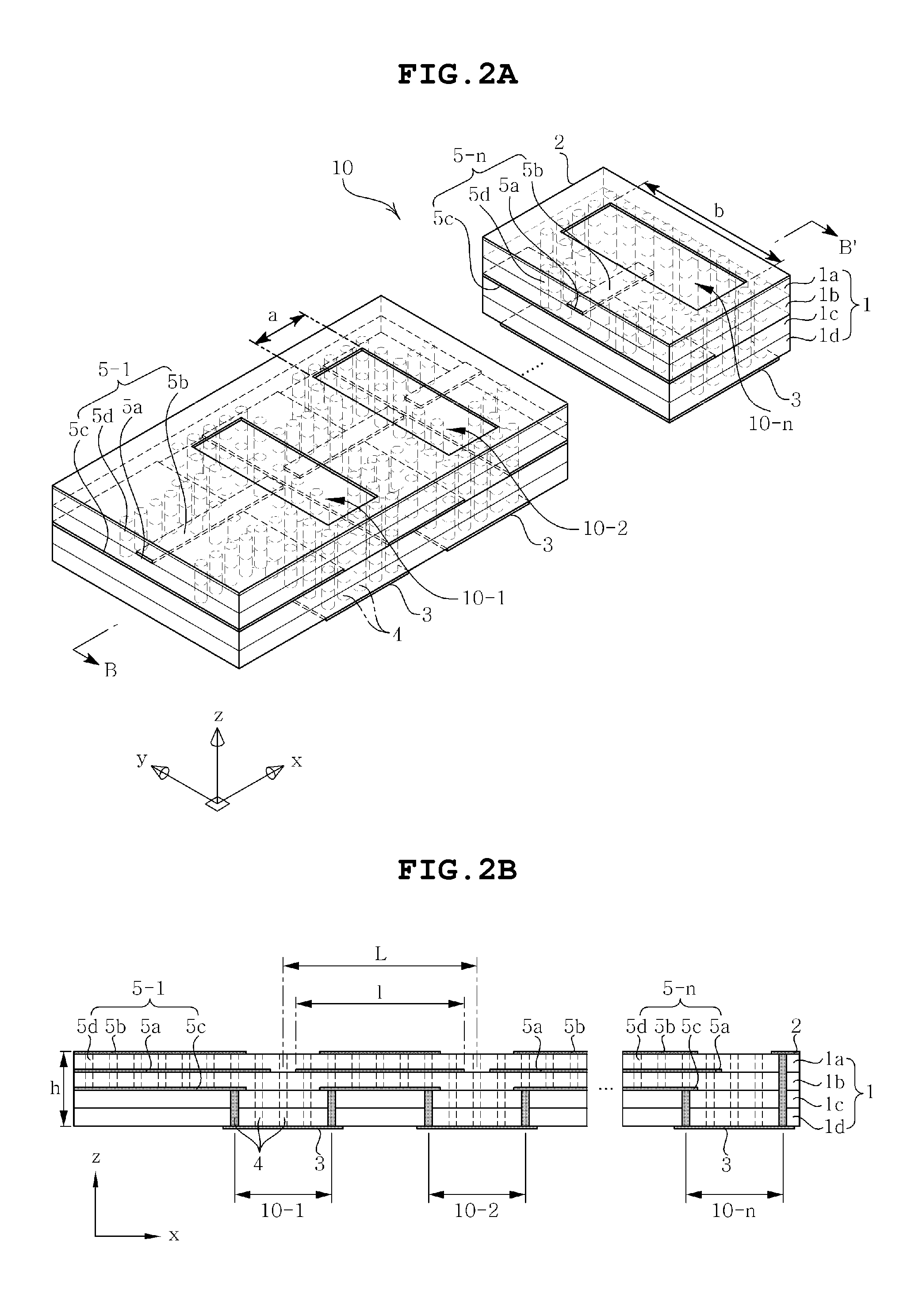
[0049]The objects, features, and advantages of the present invention will be more clearly understood from the following detailed description of the preferred embodiments taken in conjunction with the accompanying drawings. Throughout the accompanying drawings, the same reference numerals are used to designate the same or similar components, and redundant descriptions thereof are omitted. Further, in the following description, the terms “first”, “second”, “one side”, “the other side”, and the like, are used to differentiate a certain component from other components, but the configuration of such components should not be construed to be limited by the terms. Further, in the description of the present invention, when it is determined that the detailed description of the related art would obscure the gist of the present invention, the description thereof will be omitted.

[0050]Hereinafter, preferred embodiments of the present invention will be described in detail with reference to the at...


PUM


Abstract

Disclosed herein is a dielectric resonator array antenna including one or more series-feed type array elements installed to be arranged in parallel in a multilayer substrate, wherein first high frequency signals having the same or different phases or time delays are adjusted to be applied to the respective series-feed type array elements and respective radiated 1D array beams are individually used or combined to adjust beamforming of 2D array beams. Also, since the series-feed type array element is configured by connecting a plurality of dielectric resonator antennas in series, it can be easily and simply fed in series through coupling generated by the intervals between the feeding lines of the pertinent feeding unit of the plurality of dielectric resonator antennas connected in series. In addition, the broadband characteristics can be obtained by using the plurality of dielectric resonator antennas, whereby the overall antenna performance can be enhanced.

Description

CROSS REFERENCE TO RELATED APPLICATION[0001]This application claims the benefit of Korean Patent Application No. 10-2012-0087837, filed on Aug. 10, 2012, entitled “Dielectric Resonator Array Antenna”, which is hereby incorporated by reference in its entirety into this application.BACKGROUND OF THE INVENTION[0002]1. Technical Field[0003]The present invention relates to a dielectric resonator array antenna.[0004]2. Description of the Related Art[0005]Recently, research into a transmission / reception system utilizing high frequency of a millimeter wave band has been actively conducted, and such a millimeter wave frequency band has the potential of being utilized in various application fields such as short-range wireless communication, a car radar, an image system, and the like.[0006]In particular, it is anticipated that a market for a short-range wireless communication system using a 60 GHz broadband frequency and a car radar system having a 77 GHz band will be in high demand.[0007]In a...

Claims


Application Information

Patent Timeline
IPC IPC(8): H01Q13/20H01Q3/34
CPCH01Q3/34H01Q13/20H01Q3/30H01Q9/0485H01Q21/08
Inventor LEE, JUNG AUNKIM, MOONILLEE, KOOK JOO
Owner SAMSUNG ELECTRO MECHANICS CO LTD
Why Eureka
Try Eureka