Shock wave catheter system with arc preconditioning

Active Publication Date: 2014-02-20
SHOCKWAVE MEDICAL
View PDF6 Cites 46 Cited by
  • Summary
  • Abstract
  • Description
  • Claims
  • Application Information

AI Technical Summary

Benefits of technology

This patent describes a shock wave catheter system that can be used to treat blockages in blood vessels. The system includes a catheter with an inflatable balloon and two electrodes within the balloon. By delivering a high voltage across the electrodes, the system can create a rapidly expanding bubble that generates a shock wave in the balloon. The shock wave can be used to treat blockages in blood vessels by expanding the blood vessel and clearing the blockage. The system has a power source that delivers a first low voltage to grow the bubble and then a second high voltage to rapidly expand it, resulting in a highly effective treatment for blockages in blood vessels.

Problems solved by technology

With such pressures comes trauma to the vessel wall which can contribute to vessel rebound, dissection, thrombus formation, and a high level of restenosis.
Non-concentric calcified lesions can result in undue stress to the free wall of the vessel when exposed to high pressures.
That energy is then released and results in the rapid expansion of the balloon to its maximum dimension and may stress and injure the vessel walls.
Each arc results in intense heat and energy for a brief period of time.
Just a two degree Celsius elevation in temperature above body temperature can result in tissue damage.
Excessive heating of the fluid within the balloon may result.
Also, because greater applied energies create larger bubbles at the electrodes, the excessive energy will produce a larger bubble than required which can unduly stress the balloon walls.
Since the size of the electrodes must be small in order to fit into the calcified vein or artery, they are only capable of sustaining a limited numbers of high voltage pulses sufficient to form the shock wave resulting electrical arc.

Method used


Image

  • Shock wave catheter system with arc preconditioning
  • Shock wave catheter system with arc preconditioning
  • Shock wave catheter system with arc preconditioning

Examples


Embodiment Construction

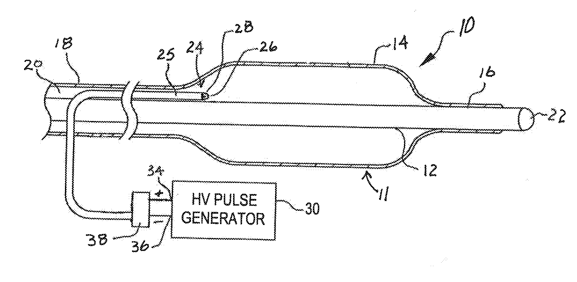
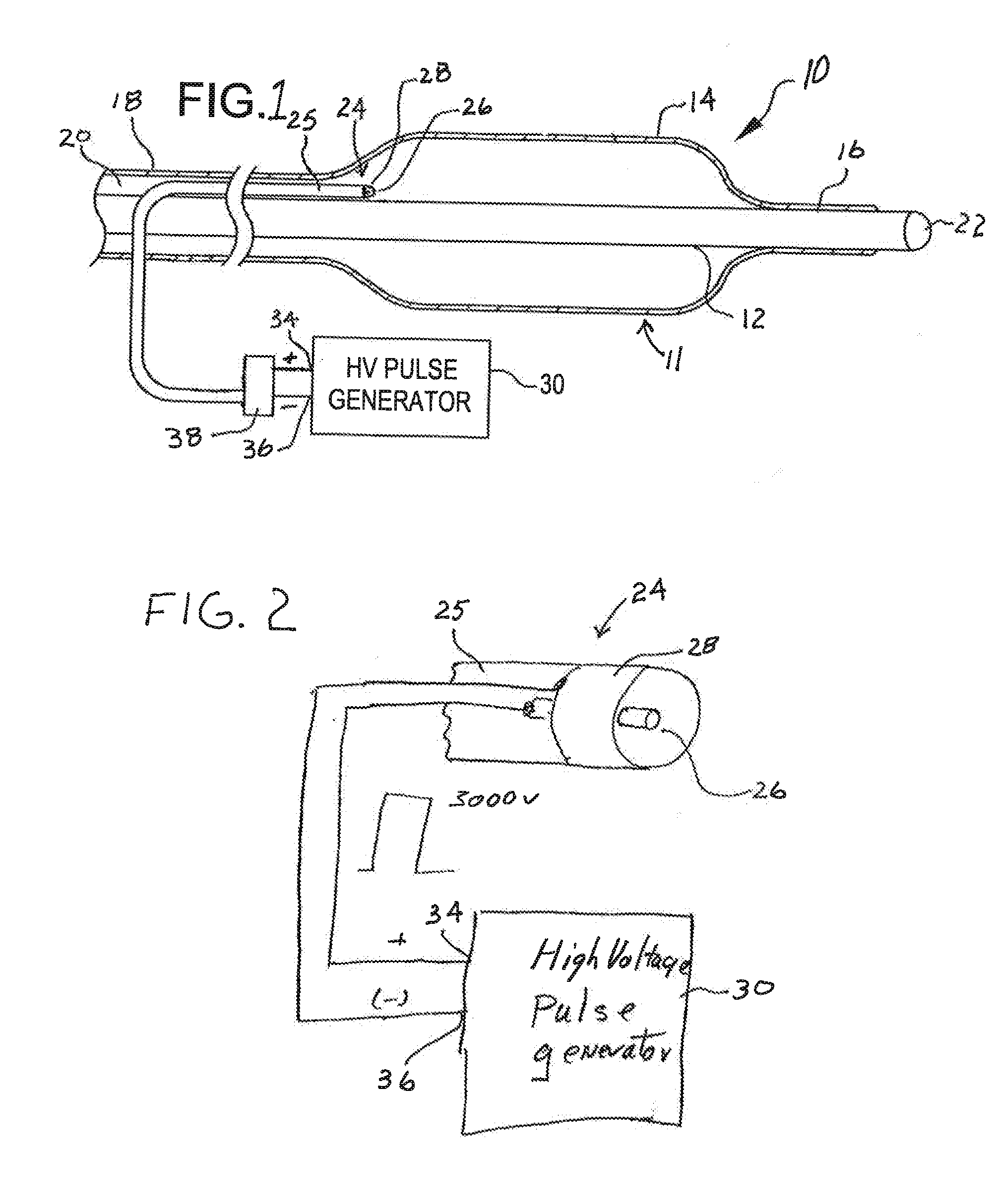
[0025]FIG. 1 is a simplified side view of an angioplasty balloon catheter system 10 of the type that may utilize various embodiments of the invention to advantage. The system 10 includes a catheter 11 and a power source 30.

[0026]The catheter 11 includes an elongated carrier, such as a hollow sheath 12 and a dilating balloon 14 formed about the sheath 12 in sealed relation thereto at a seal 16. The balloon 14 has a tubular extension 18 which forms with the sheath 12 a channel 20 for admitting a fluid into the balloon 14. The sheath 12 has a longitudinal lumen 22 through which a guide wire (not shown) may be received for directing the catheter 11 to a desired location within a vein or artery, for example.

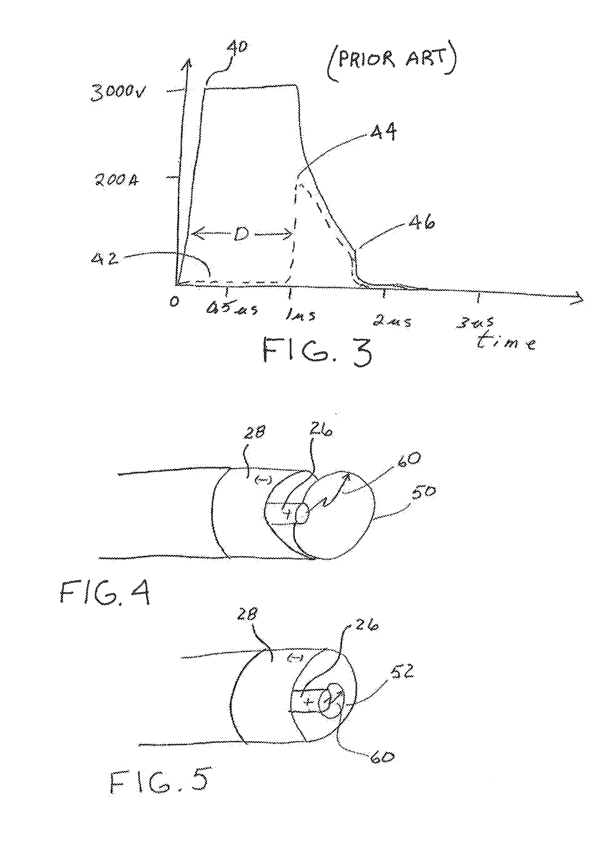
[0027]The catheter 11 further includes an arc generator 24 within the balloon 14. The arc generator, as may be best seen in FIG. 2, includes a lead 25 having a coaxially configured electrode pair including electrodes 26 and 28. As may be seen in FIG. 2, electrode 26 forms a center ele...


PUM


Abstract

A shock wave catheter system and method produces a shock wave with reduced energy. The system includes a catheter and a power source. The catheter has an elongated carrier and a balloon about the carrier in sealed relation thereto. The balloon is arranged to receive a fluid therein that inflates the balloon. The catheter further includes an arc generator including at least two electrodes within the balloon. The power source is coupled to the at least two electrodes and is configured to grow a bubble at one of the at least two electrodes and then thereafter to rapidly expand the bubble to form a shock wave within the balloon.

Description

PRIORITY CLAIM[0001]The present application claims the benefit of copending U.S. Provisional Patent Application Ser. No. 61 / 684,398, filed Aug. 17, 2012, which application is incorporated herein by reference in its entirety.BACKGROUND OF THE INVENTION[0002]The present invention relates to a treatment system for percutaneous coronary angioplasty or peripheral angioplasty in which a dilation catheter is used to cross a lesion in order to dilate the lesion and restore normal blood flow in the artery. It is particularly useful when the lesion is a calcified lesion in the wall of the artery.[0003]Calcified lesions, currently treated with angioplasty balloons, require high pressures (sometimes as high as 10-15 or even 30 atmospheres) to break the calcified plaque and push it back into the vessel wall. With such pressures comes trauma to the vessel wall which can contribute to vessel rebound, dissection, thrombus formation, and a high level of restenosis. Non-concentric calcified lesions c...

Claims


Application Information

Patent Timeline
IPC IPC(8): A61B17/225F17D3/00
CPCF17D3/00A61B17/225A61B17/2202A61B17/22022A61B2017/00159A61B2017/00176A61B2017/22062G10K15/06Y10T137/0391A61B2017/22021
Inventor ADAMS, JOHNHOLMBERG, RANDY
Owner SHOCKWAVE MEDICAL
Why Eureka
Try Eureka