Integrated method of driving a co2 compressor of a co2-capture system using waste heat from an internal combustion engine on board a mobile source

a technology of co2 compressor and co2 storage, which is applied in the direction of machines/engines, mechanical equipment, separation processes, etc., can solve the problems of limited space and weight, lack of any economies of scale, and many challenges in the management of carbon dioxide from mobile sources

Active Publication Date: 2014-02-27
SAUDI ARABIAN OIL CO
View PDF5 Cites 11 Cited by
  • Summary
  • Abstract
  • Description
  • Claims
  • Application Information

AI Technical Summary

Benefits of technology

[0040]Depending on the CO2 tank pressure and the CO2 flow which in turn, are the result of the CO2 capture rate and exhaust gas flow, it is possible to control the speed of the compressor independently of the speed of the turbine, which is the result of the exhaust flow and temperature and to provide or retrieve the extra power on the axle by the motor-generator in order to achieve a smooth and continuous operation independently of the variable operational parameters of the other components of the system.
[0041]The turbine operated by the energy recovery system and power cycle can be replaced by a turbine driven by the exhaus

Problems solved by technology

Carbon dioxide management from mobile sources presents many challenges including space and weight limitations, the lack of any economies of scale and the dynamic nature of the operation of the ICEs powering the mobile sources.
Those that address the problem of reducing CO2 emissions from mobile sources employ combustion using oxygen and provide no means for the regeneration and reuse of the CO2 capture agent, and/or make no use of waste heat recovered from a heat source.
Combustion using only oxygen requires an oxygen-nitrogen separation step which is more energy-intensive than separating CO2 from the nitrogen-containing exhaust gases resulting from the use of atmospheric air and the separation problem wo

Method used


Image

  • Integrated method of driving a co2 compressor of a co2-capture system using waste heat from an internal combustion engine on board a mobile source
  • Integrated method of driving a co2 compressor of a co2-capture system using waste heat from an internal combustion engine on board a mobile source
  • Integrated method of driving a co2 compressor of a co2-capture system using waste heat from an internal combustion engine on board a mobile source

Examples


Embodiment Construction

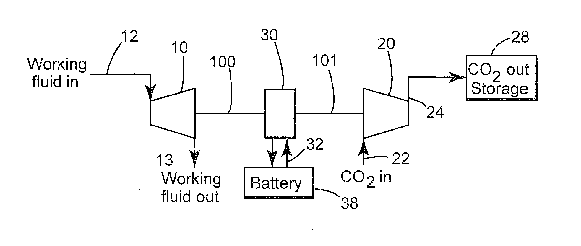
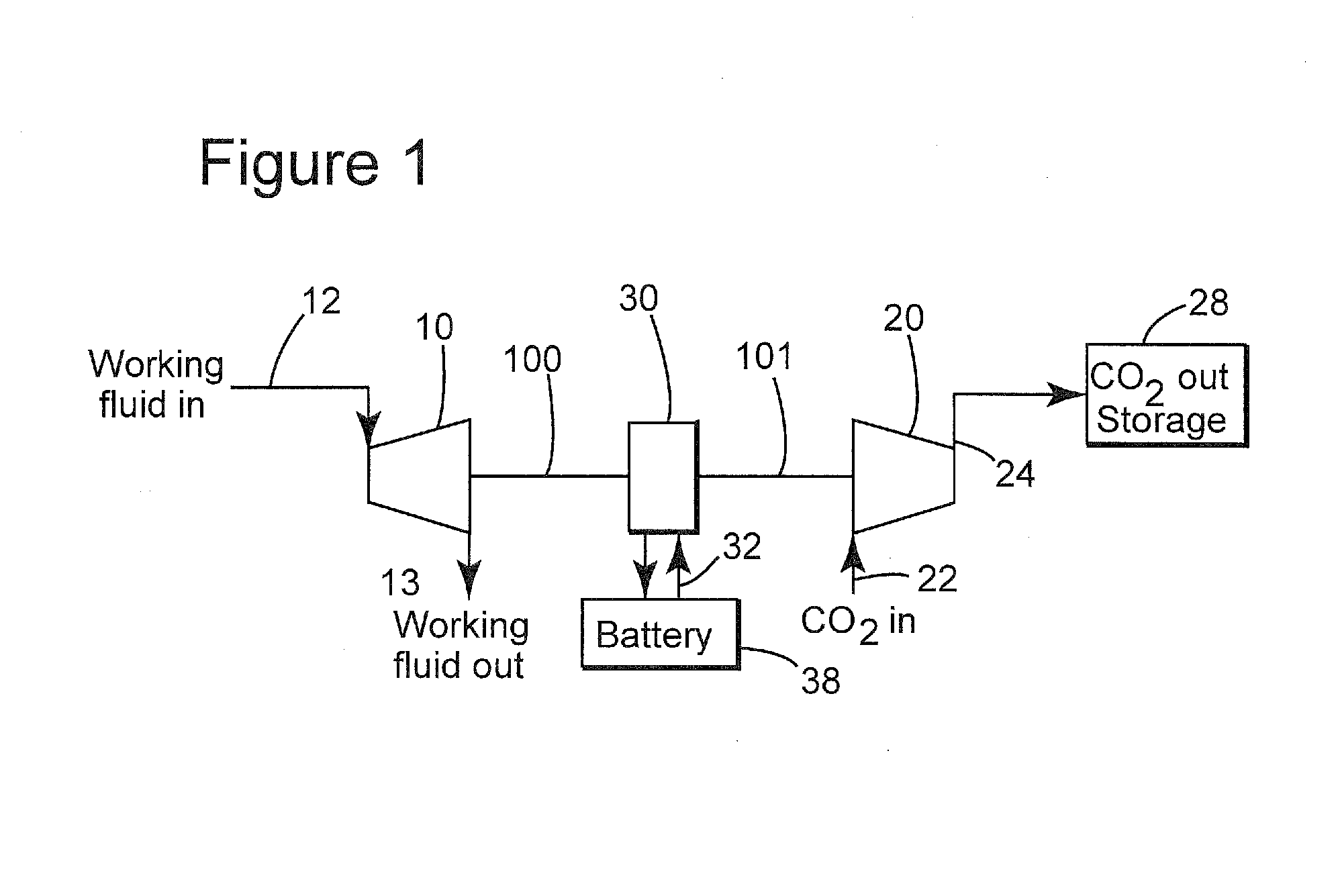
[0053]Referring to FIG. 1 which schematically illustrates an embodiment of the apparatus for effecting the inventive method, a CO2 compressor 20, a turbine 10 and a motor-generator 30 are coupled coaxially on axles or shafts 100, 101, respectively, to perform their functions. The compressor 20 receives substantially pure CO2 via conduit 22 from an upstream capture system (not shown). Compressed CO2 passes via discharge conduit 24 to CO2 storage unit 28. Turbine 10 recovers energy from an energy recovery system or power cycle. The electric motor-generator 30 adds power, as needed to operate the compressor or recovers the excess power from the turbine and converts it to electricity that is passed via conductors 32 to battery 38 where it is stored for later use, or from which it can be used directly on board the vehicle.

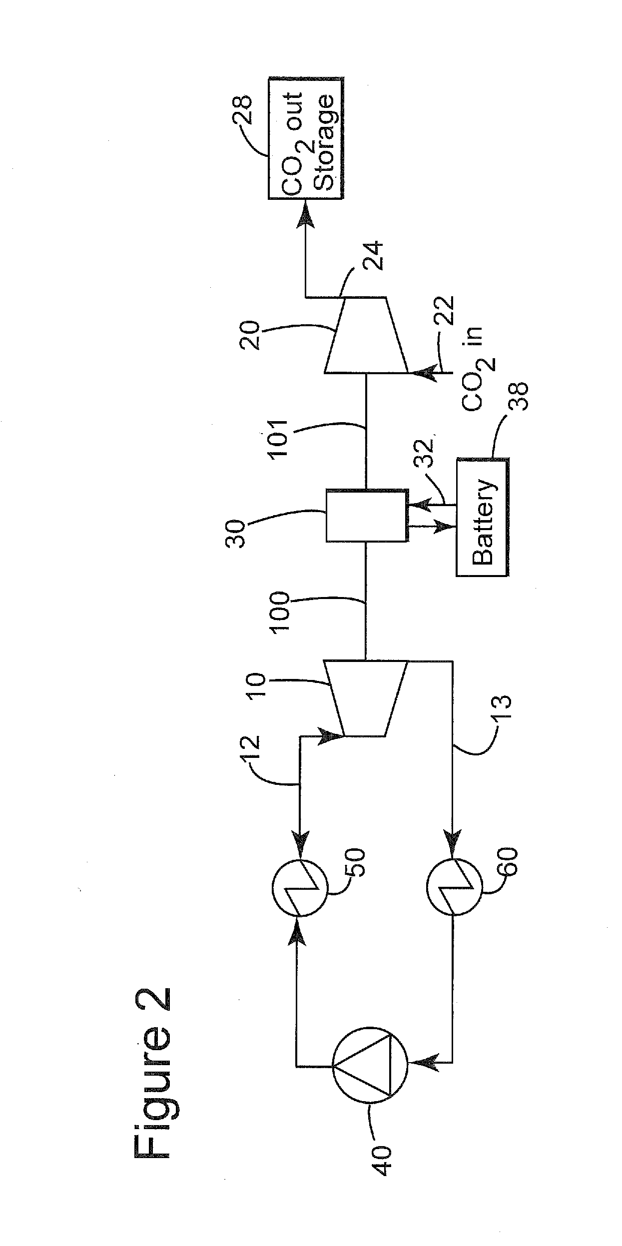
[0054]The turbine 10 can be operated by any working fluid under pressure and preferably a working fluid from an open or closed power cycle, such as a Rankine cycle or t...


PUM

PropertyMeasurementUnit
Poweraaaaaaaaaa
Speedaaaaaaaaaa

Abstract

An integrated system and method for driving a CO2 compressor to densify CO2 captured from the exhaust gas stream of an internal combustion engine on board a mobile source of CO2 includes operating a turbine that is operatively connected to the power input or drive shaft of the CO2 compressor, and operatively connecting a motor-generator to the turbine for (a) recovery of any excess power when the turbine-generated power exceeds the CO2 compressor power demand and (b) providing supplemental power when the turbine-generated power is insufficient to meet the CO2 compressor power demand.

Description

BACKGROUND OF THE INVENTION[0001]1. Field of the Invention[0002]The present invention relates to carbon dioxide (CO2) compression and storage for CO2 emission reduction purposes in mobile applications or in applications where an energy production cycle is used to produce work and where CO2 compression is required.[0003]2. Description of the Prior Art[0004]The currently accepted thinking is that global warming is due to emissions of greenhouse gases such as CO2 and methane (CH4). About a quarter of global CO2 emissions are currently estimated to come from mobile sources, i.e., automobiles, trucks, buses and trains that are powered by internal combustion engines (ICEs). This proportional contribution is likely to grow rapidly in the foreseeable future with the projected surge in automobile and truck ownership in developing countries. Accordingly, controlling CO2 emissions is very important.[0005]Carbon dioxide management from mobile sources presents many challenges including space and...

Claims


Application Information

Patent Timeline
IPC IPC(8): F04D27/00
CPCF04D27/00B01D53/1475F01N3/08F01N5/02F01N5/04F02B37/005F02B37/10B01D2252/20405B01D2252/20421B01D2252/20484B01D2257/504B01D2259/4566F01N2570/10F04D27/02Y02A50/20Y02C20/40Y02T10/12
Inventor YOUNES, MOURAD VICTORHAMAD, ESAM ZAKI
Owner SAUDI ARABIAN OIL CO
Why Eureka
Try Eureka