
Subsea Cables

Inactive Publication Date: 2014-03-06
BPP CABLES
View PDF7 Cites 24 Cited by
  • Summary
  • Abstract
  • Description
  • Claims
  • Application Information

AI Technical Summary

Benefits of technology

The present invention provides an improved water-blocking layer that surrounds the core of a subsea cable. This layer has high tensile strength and is resistant to fatigue from bending and flexure. This helps to prevent water from entering the cable and causing damage.

Problems solved by technology

Higher installation and maintenance costs which arise from the challenging environments have led the industry to favour cables with longer operational lifetimes, and which require less maintenance.
However, these conventional materials do not typically have good resistance to fatigue, and often exhibit cracks when used in heavier cables, or when deployed in dynamic applications.
However, water-blocking layers made of copper are susceptible to failure during long term use in dynamic applications.
Use of lead and lead alloys, however, is not particularly desirable for dynamic cable applications, due to the high density (and thus heavy weight) of lead.
Further, lead and its alloys lends to highly rigid structures which, in turn, result in poor fatigue performance.
Lead is also highly toxic, and thus any leachate containing lead or lead compounds is detrimental to the surrounding environment.

Method used


Image

  • Subsea Cables
  • Subsea Cables
  • Subsea Cables

Examples


example 1

[0068]Copper-ETP (electrolytic tough pitch; 99.9% Cu, minimum; UNS C11000) is one of the most widely used coppers in the cable industry due to a good combination of thermal conductivity, corrosion resistance and good workability.

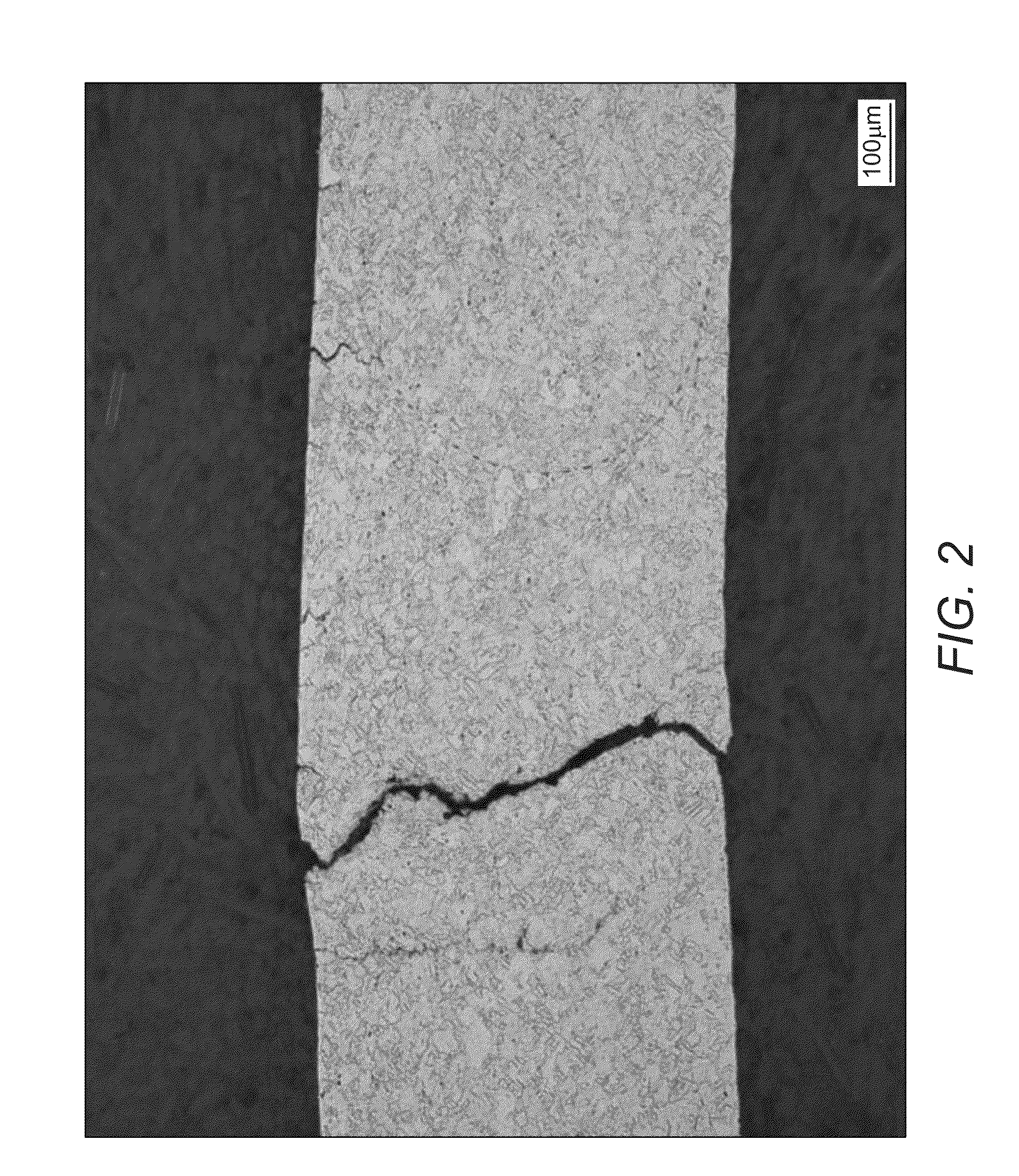
[0069]However, water blocking layers made of copper have been discovered to crack when subject to cyclic bending and stress. Any such crack through the water barrier constitutes failure of the ability of a cable to exclude water. Copper is, in particular, vulnerable to stress corrosion cracking (SCC), which is the cracking induced from the combined influence of tensile stress and a corrosive environment. Examples of SCC in copper are shown in FIGS. 2 and 3.

[0070]Without wishing to be limited by theory, SCC is caused by the interaction between copper and a particular substance, including ammonia or an ammoniacal compound, nitrates and nitrites. Such ammonia-based compounds may originate from other components of the cable, such as the polymeric sheath, insulat...

example 2

[0076]Test cables were fabricated and subjected to flex-fatigue qualification tests in order to compare conventional cables with cables of the present invention. Three core samples were manufactured, as follows.[0077]Core 1: conventionally made with a water-blocking layer made of Cu-ETP[0078]Core 2: made with a water-blocking barrier made of C70600. The water-blocking layer was bonded to the insulating layer.[0079]Core 3: made with a water-blocking barrier made of C70600. The water-blocking layer was not bonded to the insulating layer.

[0080]The copper used for the water-blocking layer in conventional cables is C11000 (UNS) [also known as C101 (British Standard) and CW004A (European Standard)].

[0081]All core samples featured 1 mm thick, longitudinally seam-welded water-blocking layers. Following manufacture and electrical acceptance tests, sample lengths of each core type were subjected to flex-fatigue testing.

[0082]Results of the flex-fatigue testing show that a bonded water-blockin...

embodiment 1

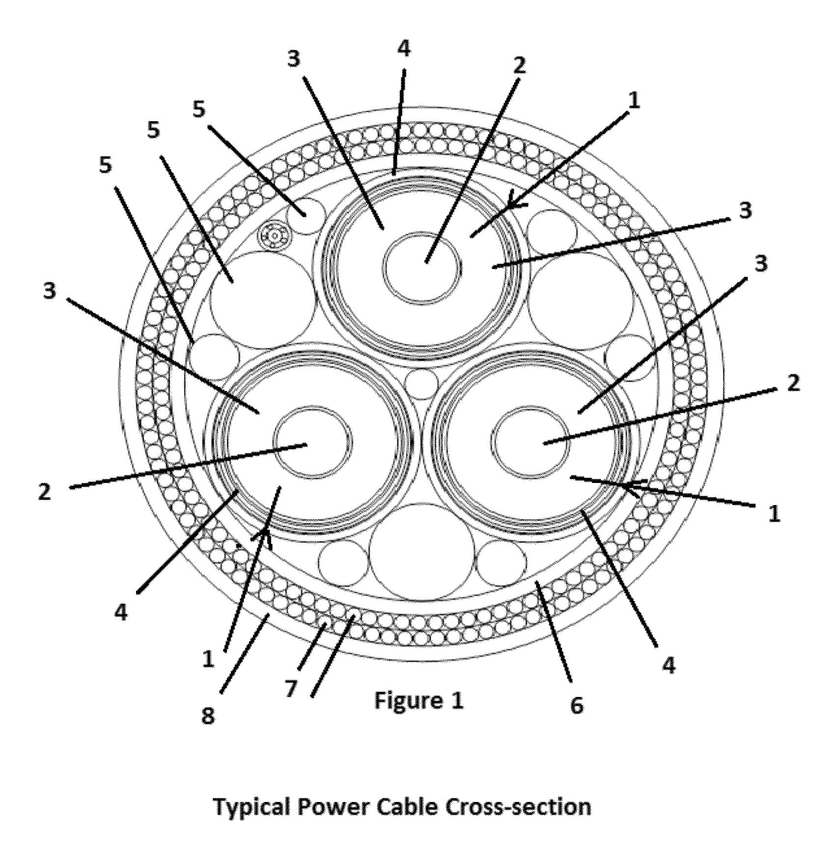
[0085]A cable comprising one or more cores, the or each core comprising: a conductor; an insulating layer; and a water-blocking layer, wherein the conductor, the insulating layer and the water-blocking layer each extend along the longitudinal axis of the core, wherein the insulating layer is axially external to the conductor, and the water-blocking layer is axially external to the insulating layer, and wherein the water-blocking layer comprises a copper alloy wherein the alloy comprises copper and nickel; copper and beryllium; copper and zinc; or copper, zinc and aluminium.


PUM

PropertyMeasurementUnit
Fractionaaaaaaaaaa
Fractionaaaaaaaaaa
Fractionaaaaaaaaaa

Abstract

Herein described is a cable from transmitting electricity, which is particularly useful for subsea applications. A method of manufacturing the cable and a method of transmitting electricity with the cable is also described.

Description

CROSS-REFERENCE TO RELATED APPLICATIONS[0001]This application claims priority to United Kingdom Patent Application No. GB1215888.7 filed on Sep. 5, 2012, which application is incorporated by reference herein in its entirety.FIELD OF INVENTION[0002]The present invention relates to a cable for conducting electricity which is particularly useful for subsea applications. The invention also relates to a water-blocking layer to protect components of such cables from water.BACKGROUND[0003]Installations in the sea, such as offshore oil platforms and wind turbines are now commonplace, and power cables are often used to transmit electricity to and from such sea-based installations to those on the land.[0004]There is growing industrial demand for power cables to operate underwater at increasing voltage and current levels. The demand is fuelled by the need for oil and gas production from fields located on the deep ocean sea bed, and by the expanding utilization of wind, tidal and ocean wave ren...

Claims


Application Information

Patent Timeline
IPC IPC(8): H01B7/14H01B13/06
CPCH01B13/062H01B7/14H01B7/2825Y02A30/14Y10T29/49117
Inventor PATEL, DARREN LINDSAY
Owner BPP CABLES
Learn More