
Method and Apparatus for Mass Analysis

a mass analysis and mass technology, applied in the field of mass spectrometry, can solve the problems of mass resolution, mass accuracy, incorrect assignment of masses and even intensities, etc., and achieve the effect of avoiding overloading and prolonging measurement tim

Active Publication Date: 2014-03-06
THERMO FISHER SCI BREMEN
View PDF17 Cites 28 Cited by
  • Summary
  • Abstract
  • Description
  • Claims
  • Application Information

AI Technical Summary

Benefits of technology

The invention improves the accuracy of measuring the total charges (or quantities) of ions in a mass analyzer by using a separate detector to obtain more accurate information. This allows for better control of the injection time and avoidance of space charge effects. The ions can be transmitted to the detector as pulses, and the detector can be used to control the injection device to avoid overloading it. The control arrangement includes a computer for controlling the operation of the ion injection device and other components of the spectrometer.

Problems solved by technology

However, this is in conflict with the fact that there is saturation at higher ion concentrations caused by space charge effects.
These space charge effects limit mass resolution and affect the mass accuracy, leading to incorrect assignment of masses and even intensities.

Method used


Image

  • Method and Apparatus for Mass Analysis
  • Method and Apparatus for Mass Analysis
  • Method and Apparatus for Mass Analysis

Examples


Embodiment Construction

[0058]In order to more fully understand the invention, various embodiments will now be described in more detail by way of examples with reference to the accompanying Figures in which:

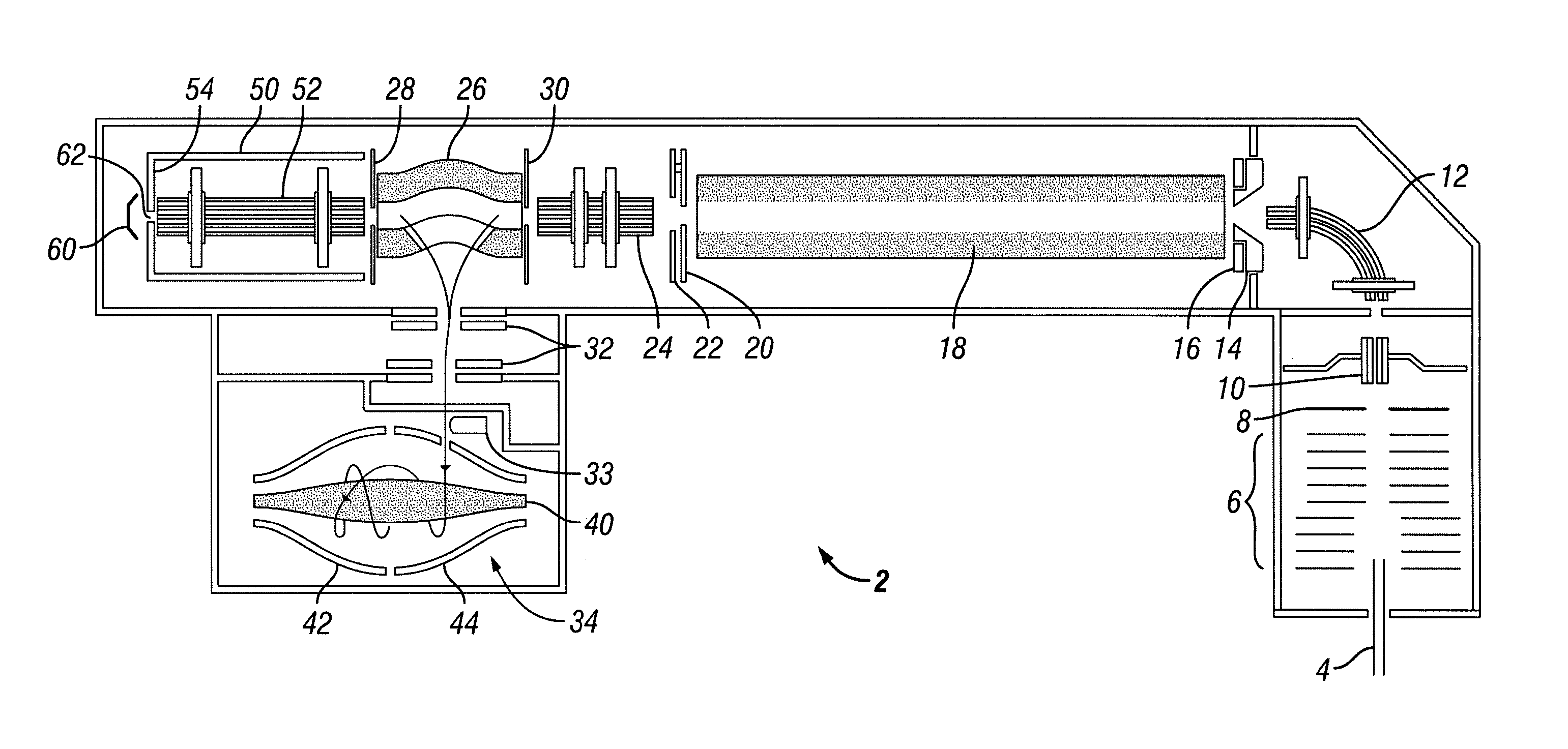
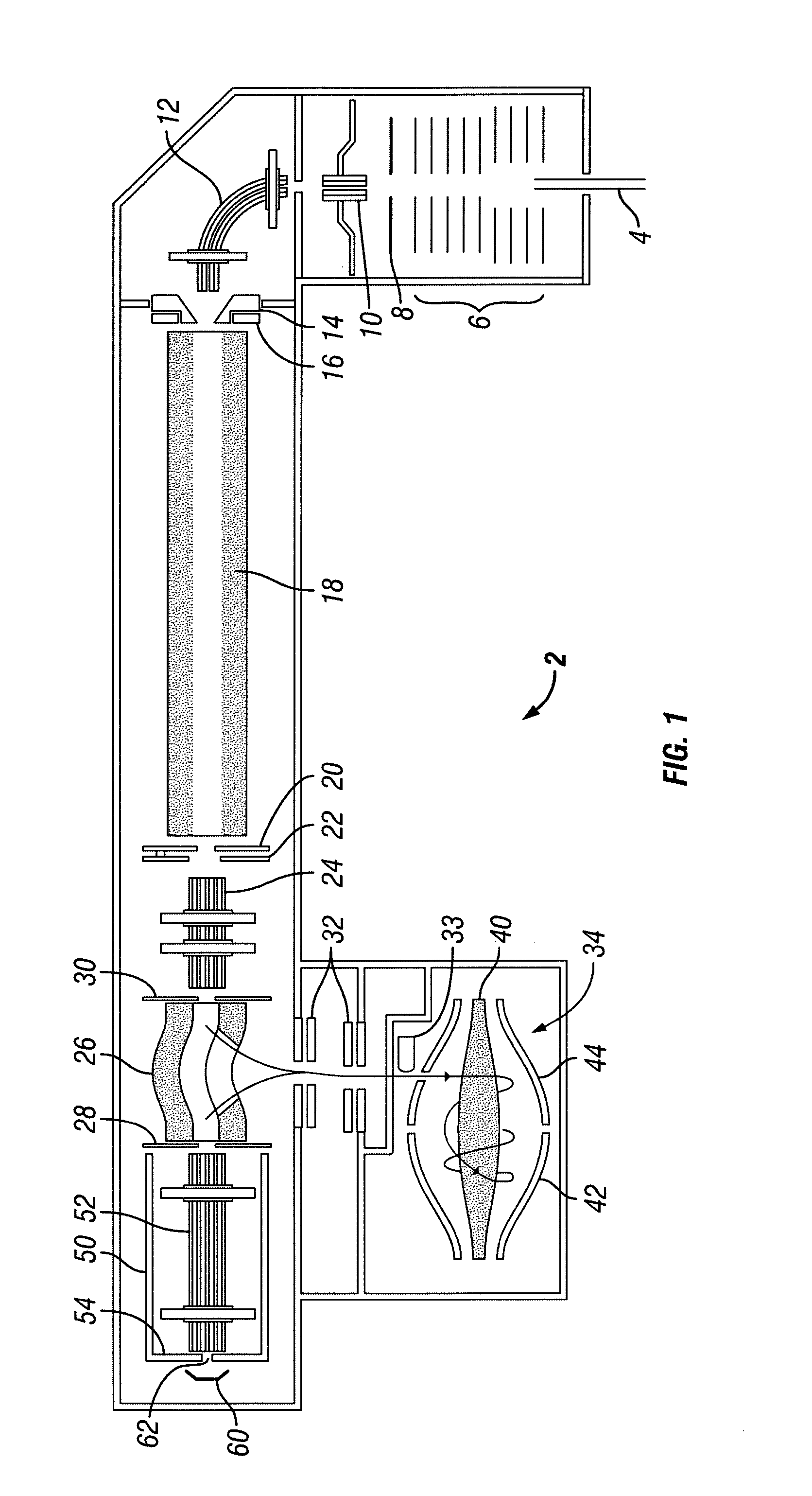
[0059]FIG. 1 shows schematically an embodiment of a mass spectrometer for carrying out the method of the present invention; and

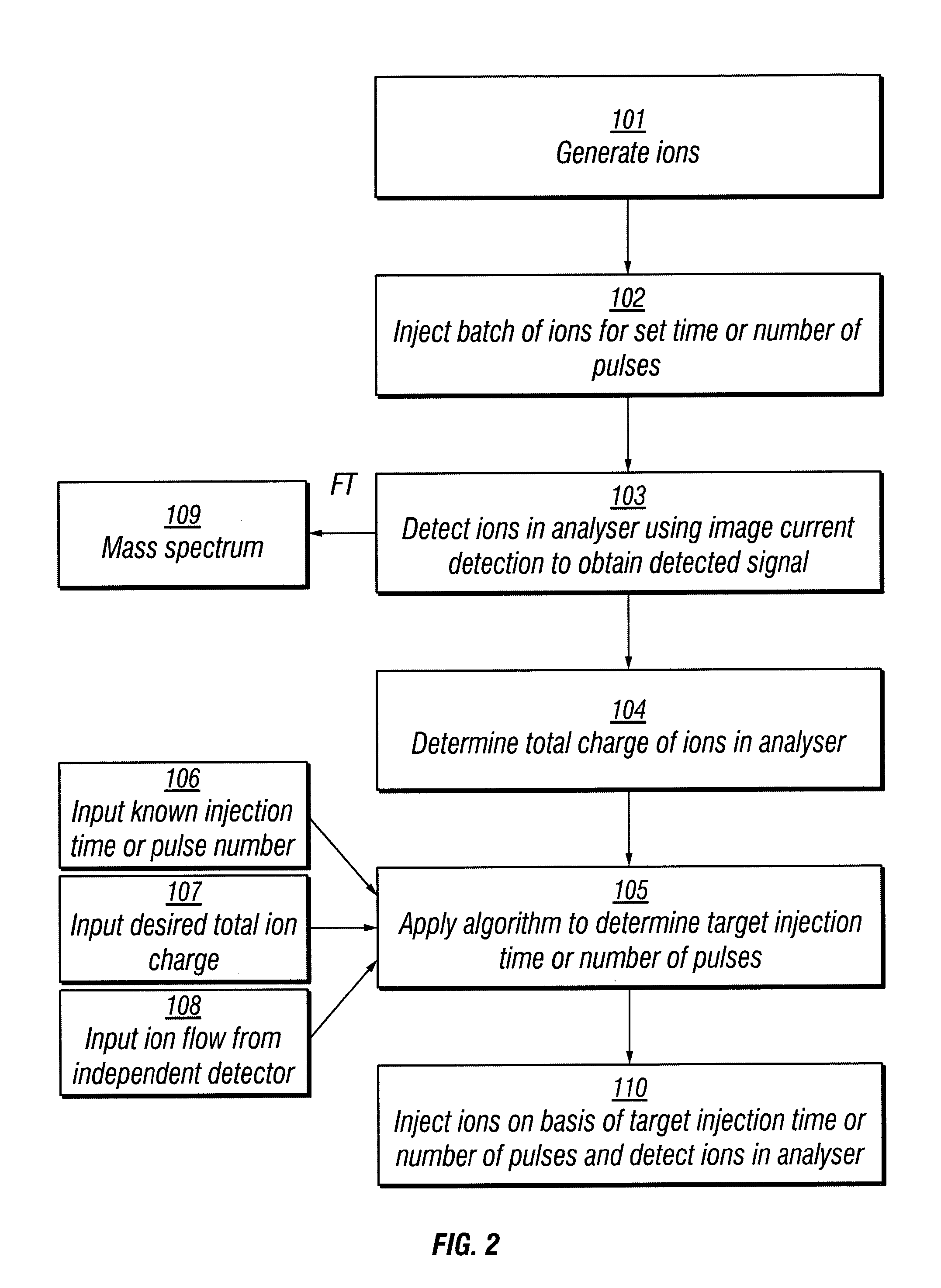
[0060]FIG. 2 shows a schematic flow chart of steps in an exemplary method according to the present invention.

[0061]FIG. 3 shows an LC-MS mass chromatogram of a HeLa sample obtained using a prior art method of automatic gain control (AGC).

[0062]FIG. 4 shows an LC-MS mass chromatogram of a HeLa sample obtained using the method of the present invention.

[0063]Referring to FIG. 1, a mass spectrometer 2 is shown in which ions are generated from a sample in an ion source (not shown), which may be a conventional ion source such as an electrospray. Ions may be generated as a continuous stream in the ion source as in electrospray, or in a pulsed manner as in a MALDI source. The sample whi...


PUM


Abstract

A method of mass analysis and a mass spectrometer are provided wherein a batch of ions is accumulated in a mass analyser; the batch of ions accumulated in the mass analyser is detected using image current detection to provide a detected signal; the number of ions in the batch of ions accumulated in the mass analyser is controlled using an algorithm based on a previous detected signal obtained using image current detection from a previous batch of ions accumulated in the mass analyser; wherein one or more parameters of the algorithm are adjusted based on a measurement of ion current or charge obtained using an independent detector located outside of the mass analyser.

Description

FIELD OF THE INVENTION[0001]The present invention relates to the field of mass spectrometry and in particular mass spectrometry employing image current detection of ions, such as FT mass spectrometry using FT-ICR cells and electrostatic traps, including electrostatic orbital traps.BACKGROUND OF THE INVENTION[0002]Numerous types of mass spectrometer employ image current detection of ions Such spectrometers commonly employ Fourier transformation of the detected image current to produce the frequency and / or mass spectrum, hence giving rise to the name Fourier transform mass spectrometry (FTMS). Such mass spectrometers typically employ ion trapping devices, with which there is a need to control the ion population in the ion trap in order to limit space charge effects.[0003]Clearly, it is desirable in FTMS to accumulate as many ions as possible in the mass analyser, in order to improve the statistics of the collected data. However, this is in conflict with the fact that there is saturati...

Claims


Application Information

Patent Timeline
Patent Type & Authority Applications(United States)
IPC IPC(8): H01J49/04
CPCH01J49/38H01J49/425H01J49/0031H01J49/04H01J49/4245H01J49/4265H01J49/027H01J49/0027
Inventor HAUSCHILD, JAN-PETERLANGE, OLIVERFROEHLICH, ULFWIEGHAUS, ANDREASKHOLOMEEV, ALEXANDERMAKAROV, ALEXANDER
Owner THERMO FISHER SCI BREMEN
Learn More