Hybrid capacitor-battery and supercapacitor with active bi-functional electrolyte

a supercapacitor and capacitor technology, applied in the field of hybrid capacitor-battery and supercapacitor with active bi-functional electrolyte, electrical devices, can solve the problem that the amount of electrolyte does not contribute to an increase in capacity

Inactive Publication Date: 2014-03-06
GOOGLE LLC +1
View PDF4 Cites 49 Cited by
  • Summary
  • Abstract
  • Description
  • Claims
  • Application Information

AI Technical Summary

Problems solved by technology

The amount of electrolyte, however, does

Method used


Image

  • Hybrid capacitor-battery and supercapacitor with active bi-functional electrolyte
  • Hybrid capacitor-battery and supercapacitor with active bi-functional electrolyte
  • Hybrid capacitor-battery and supercapacitor with active bi-functional electrolyte

Examples


Embodiment Construction

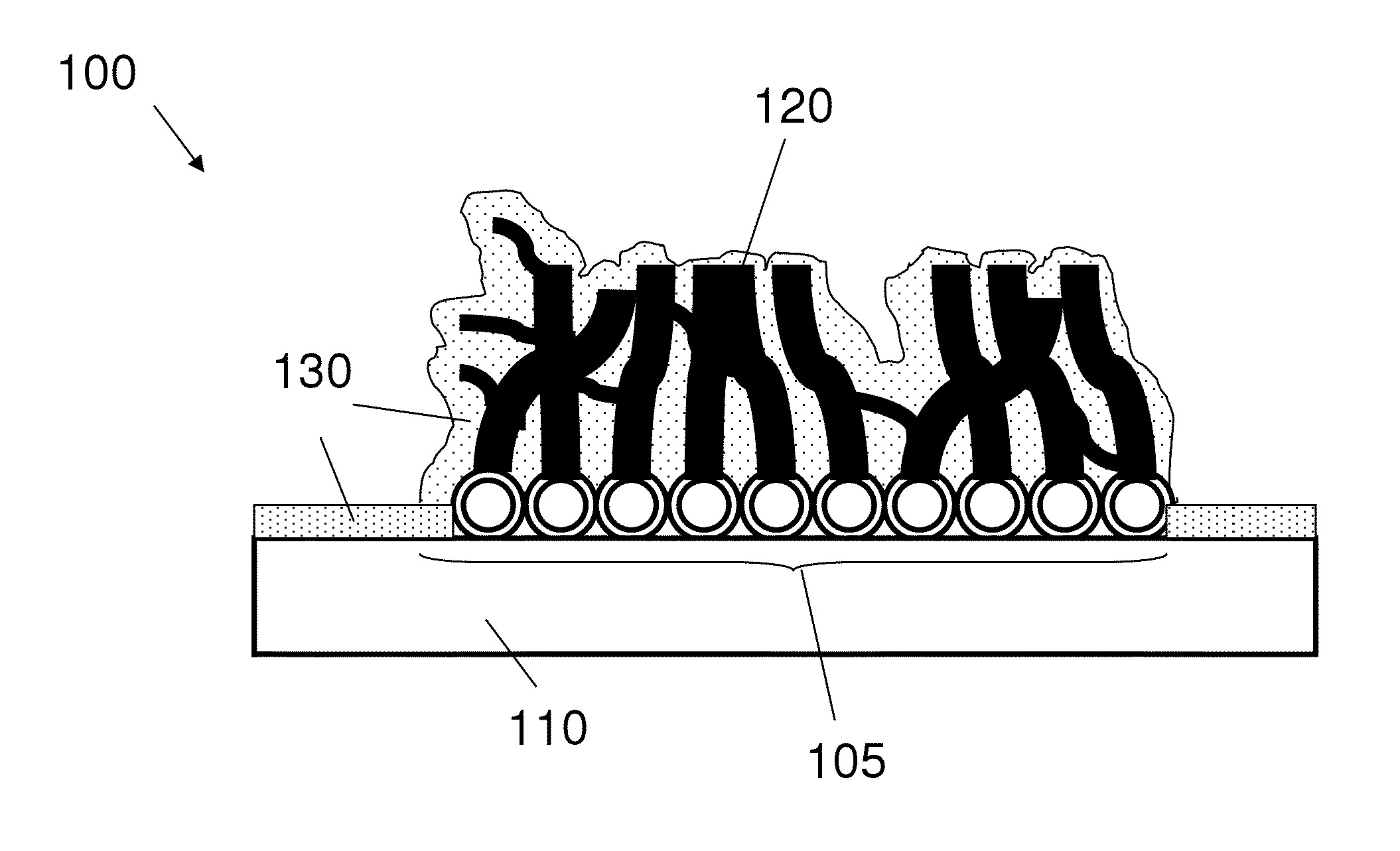
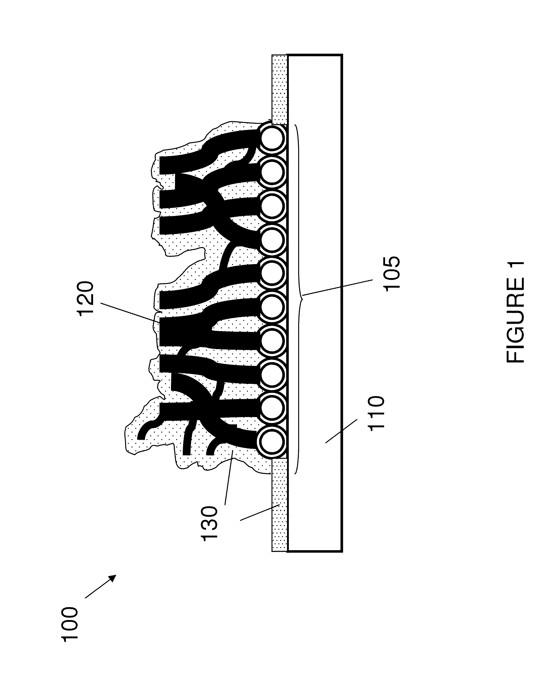
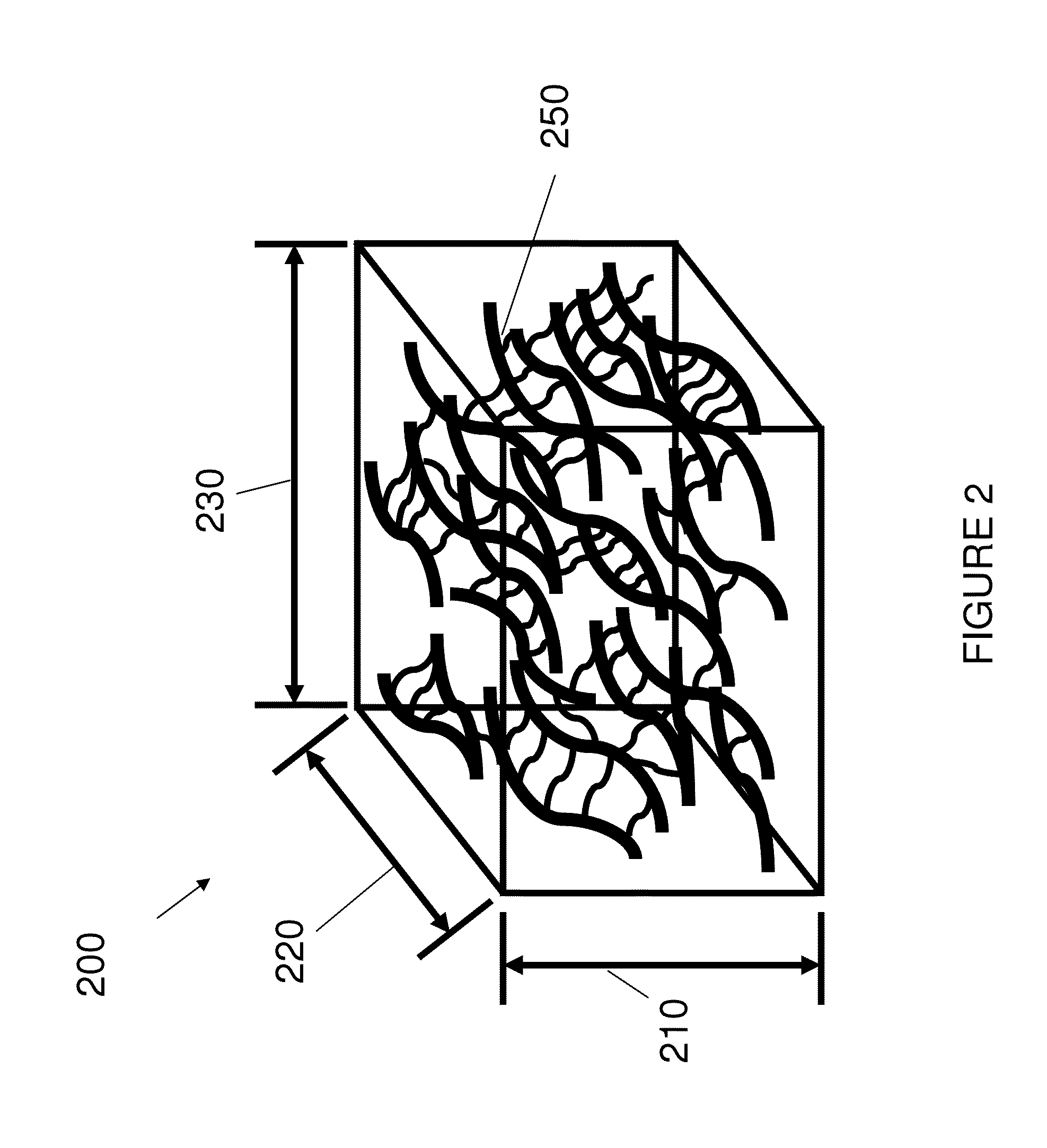
[0019]The present invention is directed, in part, to an energy storage device that includes carbon nanostructure (CNS)-infused fiber material serving as an electrode and a bi-functional electrolyte that can conduct ions and react on the electrode surfaces to contribute to the overall energy storage. In particular embodiments, the CNS-infused fiber material is a carbon fiber material, although any fiber composition can be employed in the storage devices disclosed herein.

[0020]Electrodes are the primary active material in conventional energy storage devices such as capacitors and batteries. While the electrolyte serves as a liquid wire offering ion conductivity, it does not contribute to the overall energy storage. In a conventional system, the electrolyte should fill all pores of a porous electrode material to render the electrode material active. Electrodes are desirably highly porous to reduce ionic resistance and thus enhance power and efficiency. In principle, a highly active por...


PUM


Abstract

An electrode includes a substrate having a carbon nanostructure (CNS) disposed thereon and a coating including an active material conformally disposed about the carbon nanostructure and the substrate. The electrode is used in a hybrid capacitor-battery having a bifunctional electrolyte capable of energy storage.

Description

CROSS-REFERENCE TO RELATED APPLICATIONS[0001]The present application claims the benefit of priority under 35 U.S.C. §119 from U.S. Provisional Patent Application Ser. No. 61 / 545,049 entitled “Hybrid Cap-Battery with Active Bi-Functional Electrolyte,” filed on Oct. 7, 2011, and U.S. Provisional Patent Application Ser. No. 61 / 707,738 entitled “Carbon Nanostructures and Method of Making the Same,” filed on Sep. 28, 2012, the disclosures of which are hereby incorporated by reference in their entirety for all purposes.FIELD OF THE INVENTION[0002]The present invention relates to electrochemical devices, and more particularly, electrical devices capable of energy storage.BACKGROUND OF THE INVENTION[0003]In conventional capacitors and batteries, the electrode is the active material. The electrolyte creates a continuous path for ion migrations. To increase the capacitance / capacity, the amount of electrode is increased proportionally. Since the electrode is usually highly porous to enhance io...

Claims


Application Information

Patent Timeline
IPC IPC(8): H01M12/00H01M4/13H01M4/139H01M10/054
CPCH01M12/005H01G11/28H01G11/46H01G11/48H01G11/70H01G11/86H01M4/131H01M4/136H01M4/137H01M4/663H01M4/667H01G11/36H01G11/68H01G11/40H01G11/06Y02E60/13Y02E60/10Y02P70/50
Inventor LIU, HANFLEISCHER, COREY ADAMBURGESS, WILLIAM PATRICKHETZEL, LAWRENCE P.PENSERO, GREGORY F.SHAH, TUSHAR K.
Owner GOOGLE LLC
Why Eureka
Try Eureka