Process for optimizing removal of condensable components from a fluid

Inactive Publication Date: 2014-03-20
GAS LIQUIDS ENG LTD
View PDF1 Cites 7 Cited by
  • Summary
  • Abstract
  • Description
  • Claims
  • Application Information

AI Technical Summary

Benefits of technology

The patent text discusses the problem of needing a more efficient and cost-effective dehydration process for acid gas streams. The current methods are costly and require the gas to be cooled to a temperature close to the hydrate formation temperature, which requires the addition of a thermodynamic hydrate inhibitor like glycol or methanol. There is a need for a process that can achieve efficient and cost-effective dehydration while avoiding the problems of current methods.

Problems solved by technology

Hydrates are problematic as they can cause reduced heat transfer, excess pressure drops, blockages, interruptions in production and are a safety concern.
The formation of an aqueous phase in any gas system is undesirable as it promotes corrosion, can cause gas hydrates to form and can cause mechanical and operational problems.
An aqueous phase is particularly undesirable in an acid gas system as the resulting aqueous phase will be acidic, resulting in a significant increase in the corrosion rate and usually resulting in a higher HFT than non-acid gases.

Method used


Image

  • Process for optimizing removal of condensable components from a fluid
  • Process for optimizing removal of condensable components from a fluid
  • Process for optimizing removal of condensable components from a fluid

Examples


example 1

Basic

[0051]Having reference to FIGS. 4A and 4B, in an embodiment of the invention, a water saturated acid gas feed stream 10 enters a suction stage 12 where it is compressed 14 to the suction pressure of the next stage 16. The hot compressed vapour 14 is cooled 18 with an after-cooler 20 resulting in the condensation of some of the water and other condensables in the feed stream. The condensed liquid containing water is removed 22 in a separator 24 upstream of the final stage of compression. The saturated gas 26 from the separator 24 is further compressed at 28 and is after-cooled again at 30.

[0052]A slipstream 32 from the compressed and after-cooled fluid stream is removed and isenthalpically expanded 34 across a Joule-Thomson valve (TCV) 36 to the lower suction pressure of the same stage 16 of compression. The expansion results in a temperature reduction, the magnitude of which is dependent upon the magnitude of the pressure reduction and the composition of the fluid stream. The c...

example 2

Heat Exchanger (HEX)

[0055]In cases where the composition of the feed stream, in combination with a large pressure reduction, creates a stream temperature which is below the hydrate formation temperature of the main undehydrated feed stream, the embodiment shown in FIGS. 4A and 4B can be modified to include a heat exchanger (HEX).

[0056]In reference to FIGS. 5A and 5B, the basic embodiment is modified so as to avoid the need for continuous injection of hydrate inhibitor, as is utilized in conventional refrigeration processes.

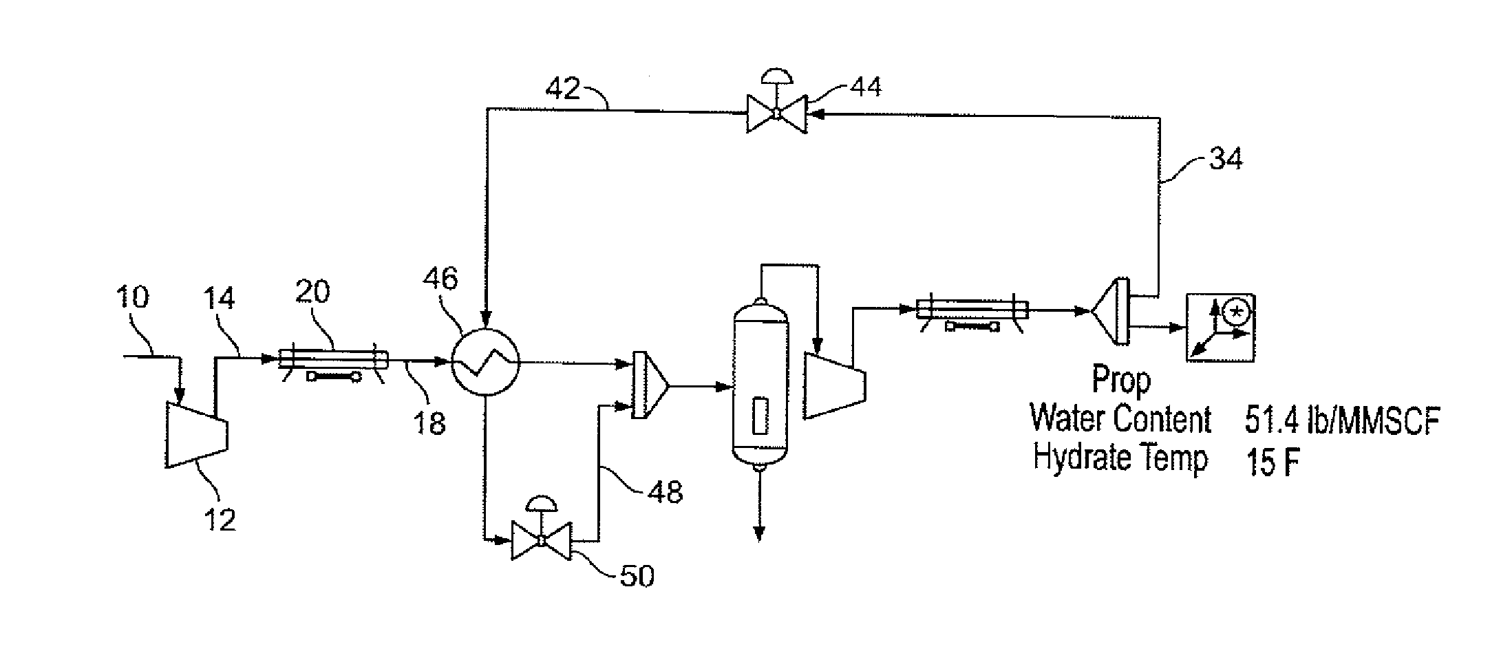
[0057]In FIGS. 5A and 5B, the slipstream 34 is partially expanded 42 across a second Joule-Thomson Valve (JTV) 44. The temperature of the partially expanded stream is thereafter raised in a heat exchanger 46 prior to further expansion of the stream 48 across the Joule-Thomson Valve (TCV) 50. Thus, the temperatures of the partially and fully expanded streams 42, 48 are maintained above the respective hydrate formation temperatures of the main undehydrated feed stre...

example 3

Low Temperature Separator (LTS)

[0061]Referring to FIGS. 6A and 6B, an embodiment of the invention utilizes an additional separator where temperature reduction is significant, as an alternate to the embodiment described in Example 2.

[0062]As shown in FIGS. 6A and 6B, the 46 and JTV 44 of FIGS. 5A and 5B are replaced with a second low temperature separator (LTS) 52. A slipstream 54 is expanded 56 across a Joule-Thomson Valve (TCV) 44. The first separator 24 is positioned to remove as much water as possible from the feed stream prior to the reintroduction of the expanded slipstream 48. The addition of hydrate inhibitor into the expanded slipstream 48 is considered when the process design requires that the temperature of the expanded slipstream be below 32° F. The early removal of the water reduces the amount of cooling required to meet the design conditions and, should conditions warrant, reduces the amount of hydrate inhibitor required.

[0063]The design hydrate formation temperature fo...


PUM


Abstract

A method for removing condensable components from a fluid containing condensable components. The method involves optimizing the temperature of an initial feed stream including the condensable components through heat exchange and cooling to condense liquids there from. The liquids are removed to form a gas stream which is then compressed and after-cooled to form a high pressure stream. A portion of the high pressure stream is expanded to form a cooled low pressure stream which is mixed with the initial feed stream to augment cooling and condensation of condensable components in the initial feed stream.

Description

TECHNICAL FIELD[0001]The present invention relates to the removal of condensables from fluid mixtures exhibiting a positive Joule-Thomson effect, and more particularly the present invention relates to the removal of, for example, water from acid gas streams, for minimizing or substantially eliminating the formation of liquid water therein so as to minimize corrosion and formation of hydrates in the gas stream, transported and injected for sequestration. A discussion of retrofit and enhanced hydrocarbon recovery is also provided.BACKGROUND ART[0002]Gas streams, such as those which result from petroleum processing or combustion processes, often contain a gas or gases which form an acid when mixed with water. Such gases are typically called “acid gases”. The most common naturally occurring acid gases resulting from petroleum processing are hydrogen sulfide (H2S) and carbon dioxide (CO2). Typical acid gases derived from combustion / oxidation / pyrolysis processes are carbon dioxide (CO2), ...

Claims


Application Information

Patent Timeline
IPC IPC(8): F25J3/08
CPCB01D53/002B01D53/265B01D2257/7022B01D2257/80F25J3/062F25J3/065F25J3/08F25J2220/66F25J2220/68
Inventor MCKAY, N. WAYNEMADDOCKS, JAMES
Owner GAS LIQUIDS ENG LTD
Why Eureka
Try Eureka