Internal combustion engine with direct air injection and pivoting valve

a technology of pivoting valve and internal combustion engine, which is applied in the direction of machines/engines, liquid fuel feeders, engine components, etc., can solve the problems of low efficiency, low power-to-weight ratio, and internal combustion engine manufacturing, so as to improve torque capability, improve efficiency, and increase output power-to-weight ratio

Inactive Publication Date: 2014-03-20
SHEHTER PAVEL +1
View PDF19 Cites 3 Cited by
  • Summary
  • Abstract
  • Description
  • Claims
  • Application Information

AI Technical Summary

Benefits of technology

The present invention provides an improved internal combustion engine that is more efficient, has greater output power to weight ratio, and improved torque capabilities. It uses an external air compressor and / or compressed air reservoir to inject compressed air directly into the combustion cavity, obviating the need for intake valves. The engine avoids the reciprocation of relatively large masses therein, thereby reducing fuel efficiency and vibrations. It requires fewer parts and without the need for complex types of valve mechanisms. The invention also includes a rotary engine with interchangeable rotors, a hybrid vehicle with electric motor in each wheel, and an automatic parking system for hybrid vehicles. The invention utilizes a Roots-type supercharging compressor configuration and a separate electric motor for each wheel for greater maneuverability, decreased size and weight, and improved power and performance.

Problems solved by technology

Presently, the internal combustion engines being manufactured generally suffer from a plethora of problems, such as excessive weight and size, low efficiency, low power-to-weight ratio, low torque, high fuel consumption, high levels of air pollution, excessive noise and vibration, high complexity and large number of parts, which leads to decreased reliability and durability of the engine.

Method used


Image

  • Internal combustion engine with direct air injection and pivoting valve
  • Internal combustion engine with direct air injection and pivoting valve
  • Internal combustion engine with direct air injection and pivoting valve

Examples


Embodiment Construction

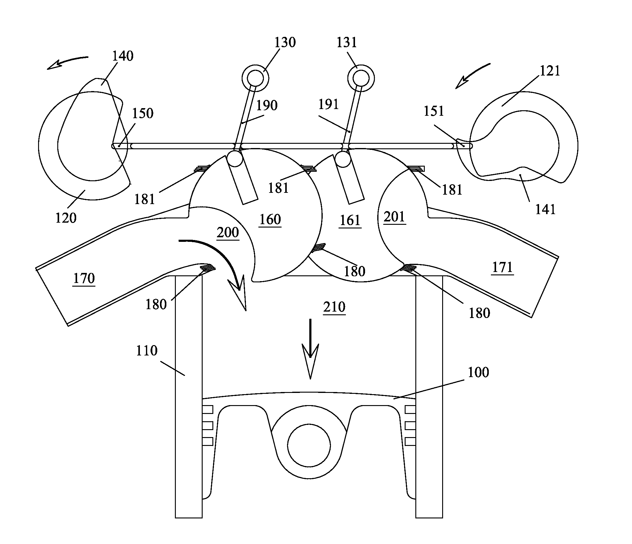
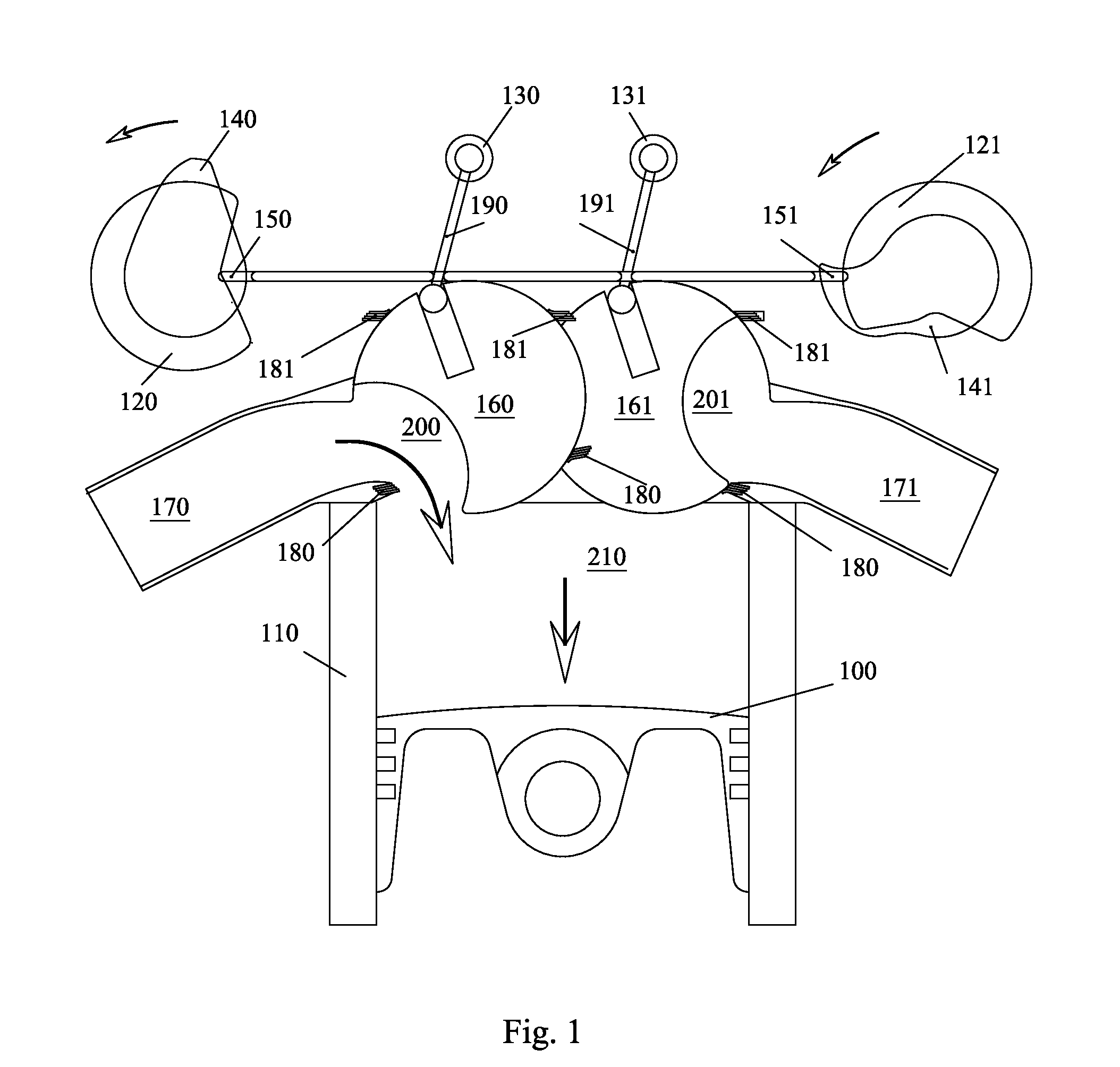
[0026]Referring to the drawings, particularly to FIG. 1, which shows a valve mechanism for a machine such as an internal combustion engine, which requires distribution of gases, a variable pivoting valve mechanism can be seen, wherein valve opening and closing can be achieved by pivoting it by means of a rocker arm and plunger. Gas distribution timing and phases are regulated by moving the axis of the rocker arm. FIG. 1 shows the fuel-air mixture intake stroke, the engine crankshaft (not shown), which, while turning, moves piston 100 down along the axis of cylinder 110, creating low pressure in cavity bore 210 within cylinder 110. Cam 120 of the left distribution camshaft by means of plunger 150 and rocking lever 190 turns intake spherical valve 160 with its intake valve cavity 200 counter-clockwise and opens gas mixture access through intake pipe 170. Thus, gas mixture from intake pipe 170 enters cavity bore 210 of cylinder 110. At the end of the intake stroke of the cycle, cam 120...


PUM


Abstract

An internal combustion engine is provided. The engine comprises at least one combustion chamber. The engine is suitable for various types of fuel. The engine, depending on fuel type, may have at least one spark plug. The engine uses an external source of compressed oxidant, such as air, which is delivered from a compressor and / or pressurized storage tank. Compressed oxidant, such as air, is delivered directly into the combustion chamber. Fuel is delivered directly into the combustion chamber. Oxidant and fuel mixture is ignited either by means of a spark plug, laser ignition, or by other means, or ignites spontaneously, depending on fuel type and pressure in the combustion chamber. The engine may comprise at least one cylinder, or may be of rotary or other type. A hybrid vehicle based on such an engine is provided. An automatic parking system for such a vehicle is provided.

Description

CROSS-REFERENCE TO RELATED APPLICATIONS[0001]This application claims the benefit under 35 USC §119(e) of U.S. application Ser. No. 13 / 427,942 filed Mar. 23, 2012 and titled “Internal combustion engine with direct air injection.”BACKGROUND OF THE INVENTION[0002]This invention pertains to the field of internal combustion engines. Presently, the internal combustion engines being manufactured generally suffer from a plethora of problems, such as excessive weight and size, low efficiency, low power-to-weight ratio, low torque, high fuel consumption, high levels of air pollution, excessive noise and vibration, high complexity and large number of parts, which leads to decreased reliability and durability of the engine. The present invention endeavors to solve these problems to some extent, improving the relevant parameters substantially.BRIEF SUMMARY OF THE INVENTION[0003]The principal objects of the present invention are: to provide an improved internal combustion engine; to also provide ...

Claims


Application Information

Patent Timeline
Patent Type & Authority Applications(United States)
IPC IPC(8): F02B3/04
CPCF02B3/04F02B21/00
Inventor SHEHTER, PAVELBRODSKY, SEVA
Owner SHEHTER PAVEL
Why Eureka
Try Eureka