RF system, magnetic filter, and high voltage isolation for an inductively coupled plasma ion source

a plasma ion source and inductive coupling technology, applied in the field of plasma ion sources, can solve the problems of limiting reducing the usefulness of removing volumes with dimensions exceeding 10 m, so as to improve the effect of magnetic filtering and high voltage isolation

Active Publication Date: 2014-03-20
OREGON PHYSICS
View PDF45 Cites 25 Cited by
  • Summary
  • Abstract
  • Description
  • Claims
  • Application Information

AI Technical Summary

Benefits of technology

[0012]The present invention provides a solution for providing RF power to inductively coupled ion sources as well as improved magnetic filtering and high voltage isolation to plasma ion sources biased to high voltage.
[0015]A gas feed insulator design that improves the high voltage standoff by reducing the electric field along the insulator path is further disclosed. This design results in a short path within the insulator in the direction of the electric field to minimize avalanche breakdown within the insulator.
[0016]Finally, the patent describes an ion source that allows for negative ion extraction (or positive ions). The negative ion extraction is facilitated by the transverse magnetic field, that's created by the magnetic circuit. Optimal negative ion generation is achieved with an RF frequency that's greater than 40 MHz. Impedance matching at 40 MHz or above, is made significantly easier by using fixed capacitors and a variable RF frequency to achieve the matching. Variable frequency impedance tuning also allows the impedance match circuit to be more compact, lower complexity and power efficient. Variable frequency tuning eliminates the need for mechanically adjustable capacitors that require servo or stepper motors to drive them, thus minimizing the complexity of the impedance matching device.

Problems solved by technology

However, conventional FIB systems typically have a maximum removal rate of ˜5 μm3 / s that limits their usefulness for removing volumes with dimensions exceeding 10 μm.
Conventional FIB systems are further limited by the low angular intensity of the ion source, so at large beam currents the beam size dramatically increases from spherical aberration.
Negatively charged oxygen ion beams, not only enhance the yield of positively charged secondary ions, but also result in minimal sample charge buildup when the sample is a dielectric material.
Duoplasmatrons also produce ion beams with a relatively large axial energy spread (˜15 eV), which is also problematic when endeavoring to produce high spatial resolution focused primary ion beams.
One issue in the design of plasma ion sources is how to create an optimum magnetic field near the extraction aperture while a high voltage bias is applied to the plasma chamber.
A second issue is how to provide radio frequency power to the antenna when the effective impedance of the plasma is very low compared to common RF power supply output impedances.
This is especially problematic because the effective impedance of the plasma varies with plasma chamber gas pressure, gas composition, and the change of state during plasma ignition.
A third problem is how to introduce gas into a reactor chamber that is biased to a high voltage without having high voltage breakdown through the input gas line.

Method used


Image

  • RF system, magnetic filter, and high voltage isolation for an inductively coupled plasma ion source
  • RF system, magnetic filter, and high voltage isolation for an inductively coupled plasma ion source
  • RF system, magnetic filter, and high voltage isolation for an inductively coupled plasma ion source

Examples


Embodiment Construction

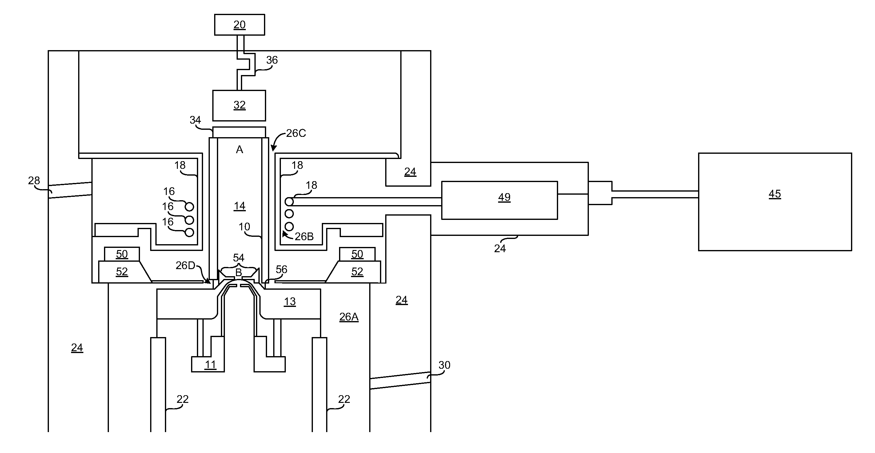
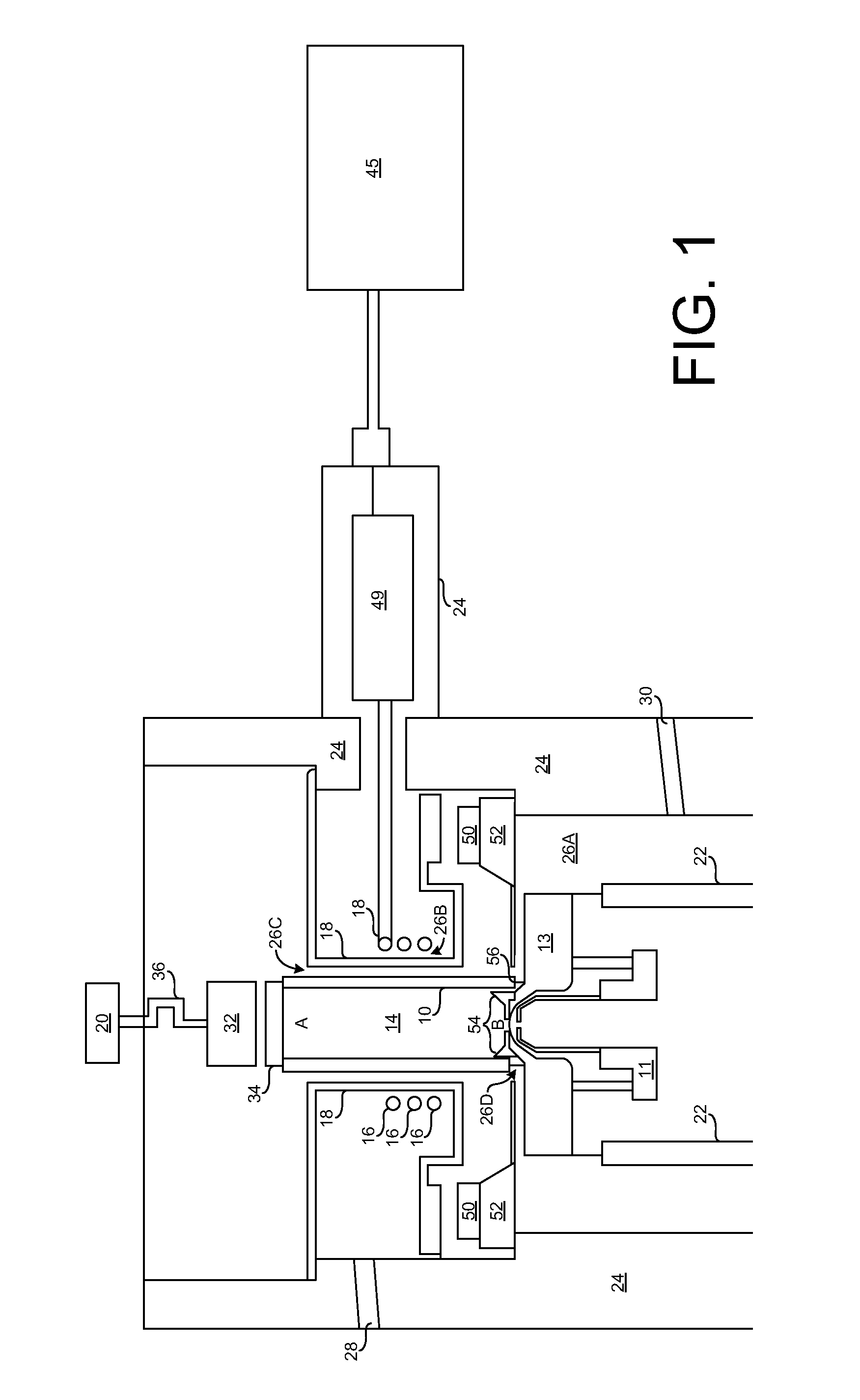
[0021]FIG. 1 shows an inductively coupled plasma source that includes a ceramic tube 10, enclosing the plasma chamber 14, welded between a first upstream metal flange 34 and a second downstream vacuum flange 13. Windings of an RF antenna 16 are wrapped around, but electrically isolated (e.g. slightly spaced) from, the cylindrical outer walls of ceramic tube 10. As will be further appreciated through the description below, RF antenna 16 is further electrically isolated from the cylindrical outer walls of the ceramic tube 10 by filling of the space between them with a dielectric fluid. A split Faraday shield 18 surrounds the cylindrical outer walls of ceramic tube 10 and is interposed between the RF antenna 16 and the ceramic tube 10. Shield 18 includes a plurality of slits through the wall of the shield 18 facing the ceramic tube 10, with a space between the shield 18 and tube 10 being filled with the dielectric fluid.

[0022]A gas inlet 20 communicates with an upstream opening A in th...


PUM


Abstract

In a plasma ion source having an induction coil adjacent to a reactor chamber for inductively coupling power into the plasma from a radio frequency power source and designed for negative and positive ion extraction, a method for operating the source according to the invention comprises providing radio frequency power to the induction coil with a RF amplifier operating with a variable frequency connected to a matching network mainly comprised of fixed value capacitors. In this device the impedance between the RF power source and the plasma ion source is matched by tuning the RF frequency rather than adjusting the capacitance of the matching network. An option to use a RF power source utilizing lateral diffused metal oxide semiconductor field effect transistor based amplifiers is disclosed.

Description

CROSS-REFERENCES TO RELATED APPLICATIONS[0001]This application claims the benefit of U.S. Provisional Patent Application No. 61 / 701,495, filed Sep. 14, 2012, whose contents are incorporated herein for all purposes.BACKGROUND OF THE INVENTION[0002]1. Field of the Invention[0003]This invention relates generally to plasma ion sources and more particularly to methods for providing RF power, magnetic filtering, and high voltage isolation to an inductively coupled plasma ion source[0004]2. Description of the Prior Art[0005]Focused ion beam (FIB) tools are used for nanometer scale precision material removal. The benefits of FIB tools include nano-scale beam placement accuracy, a combined imaging and patterning system for accurate sample registration and pattern placement, and low structural damage of the area surrounding the removed volume. However, conventional FIB systems typically have a maximum removal rate of ˜5 μm3 / s that limits their usefulness for removing volumes with dimensions e...

Claims


Application Information

Patent Timeline
Patent Type & Authority Applications(United States)
IPC IPC(8): H05H1/24
CPCH05H1/24H05H1/46H01J37/08H01J37/32082H01J27/16H01J49/105H01J49/142H05H1/4652
Inventor BOSWELL, RODERICK W.SMITH, NOEL S.TESCH, PAUL P.MARTIN, NOEL P.
Owner OREGON PHYSICS
Why Eureka
Try Eureka