Once-through steam generator

a generator and steam technology, applied in water supply installation, steam separation arrangements, lighting and heating apparatuses, etc., can solve the problems of reducing the service life of the boiler, so as to reduce the problem of thermal fatigue stress, prevent or minimize thermal shock.

Inactive Publication Date: 2014-05-08
VOGT POWER INT
View PDF6 Cites 14 Cited by
  • Summary
  • Abstract
  • Description
  • Claims
  • Application Information

AI Technical Summary

Benefits of technology

[0008]The OTSG may also include a steam separating device, such as a loop seal separator, that is positioned in-line with the heat transfer tubes of the tube bundle between the evaporator section and the superheater section. Through use of this loop seal separator, the combustion turbine may be started with water remaining in the heat transfer tubes of the tube bundle. During start-up, hot water and saturated steam thus exit the evaporator section via piping and are delivered to the loop seal separator. Hot water collected in the loop seal separator is then delivered to the feedwater delivery piping, while steam collected in the loop seal separator is returned to the superheater section. Furthermore, during normal design operation, the positioning of the loop seal separator between the evaporator section and the superheater section means only dry steam (with a small degree of superheat) will enter the loop seal separator. In any event, during a hot wet start-up, hot water collected in the loop seal separator is delivered to and mixed with cold feedwater entering the OTSG, thus preventing or at least minimizing thermal shock that would otherwise result from cold feedwater entering hot heat transfer tubes of the tube bundle in the OTSG.
[0009]The OTSG may also include a start-up module, which is a set of heat transfer tubes positioned in the duct near the inlet end for use in a dry start-up, when the OTSG is hot, but there is no water in the heat transfer tubes of the tube bundle. Specifically, rather than using the traditional scheme of sending cold feedwater into the hot heat transfer tubes of the tube bundle, cold feedwater is first delivered into the start-up module. Because of the positioning of the start-up module in the duct near the inlet end, superheated steam is initially generated in the start-up module, and that superheated steam then exits the start-up module and is delivered back to the feedwater delivery piping where it enters the OTSG to begin a controlled cool-down in the upper inlet areas of the OTSG. As the rate of cold feedwater to the start-up module is increased, the outlet degree of superheat temperature of the steam from the start-up module decreases, until there is a phase change, and hot water is exiting the start-up module and delivered back to the feedwater delivery piping. This hot water exiting the start-up module is then mixed into a cold feedwater stream into the OTSG. Thus, the rate change of the temperature of the feedwater entering the OTSG is controlled, which minimizes the problem of thermal fatigue stresses in the upper inlet areas of the OTSG.

Problems solved by technology

Second, evaporator sections convert the water heated in the economizer sections into saturated steam.
Also, because the steam drum walls in an HRSG are prone to fatigue failures that result from rapid temperature change, an OTSG unit can usually start up faster.
At the same time, however, there are disadvantages with respect to the use of an OTSG.
Therefore, costly boiler feedwater must be drained from the tube bundle at every shutdown.
This introduction of cold feedwater into hot heat transfer tubes causes large thermal fatigue stresses, dramatically reducing cycle life of the heat transfer tubes in the upper inlet areas.
Another problem of traditional OTSG designs is that during rapid transient load changes of the combustion turbine, including a trip or a shutdown, there is potential for large slugs of water to enter the lower superheating section of the OTSG.
This can also cause large thermal stresses, which further reduces cycle life in these critical areas.

Method used


Image

  • Once-through steam generator
  • Once-through steam generator
  • Once-through steam generator

Examples


Embodiment Construction

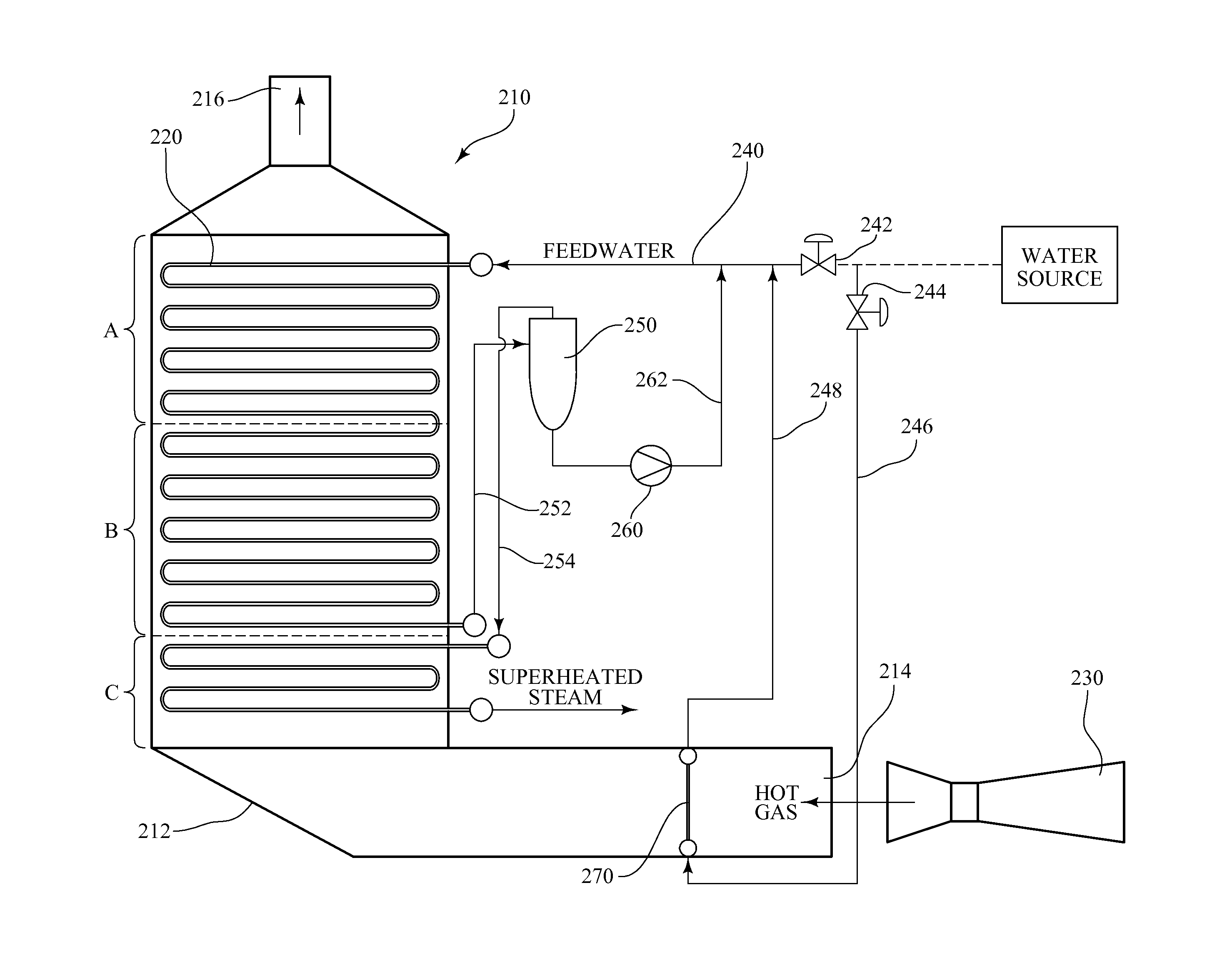
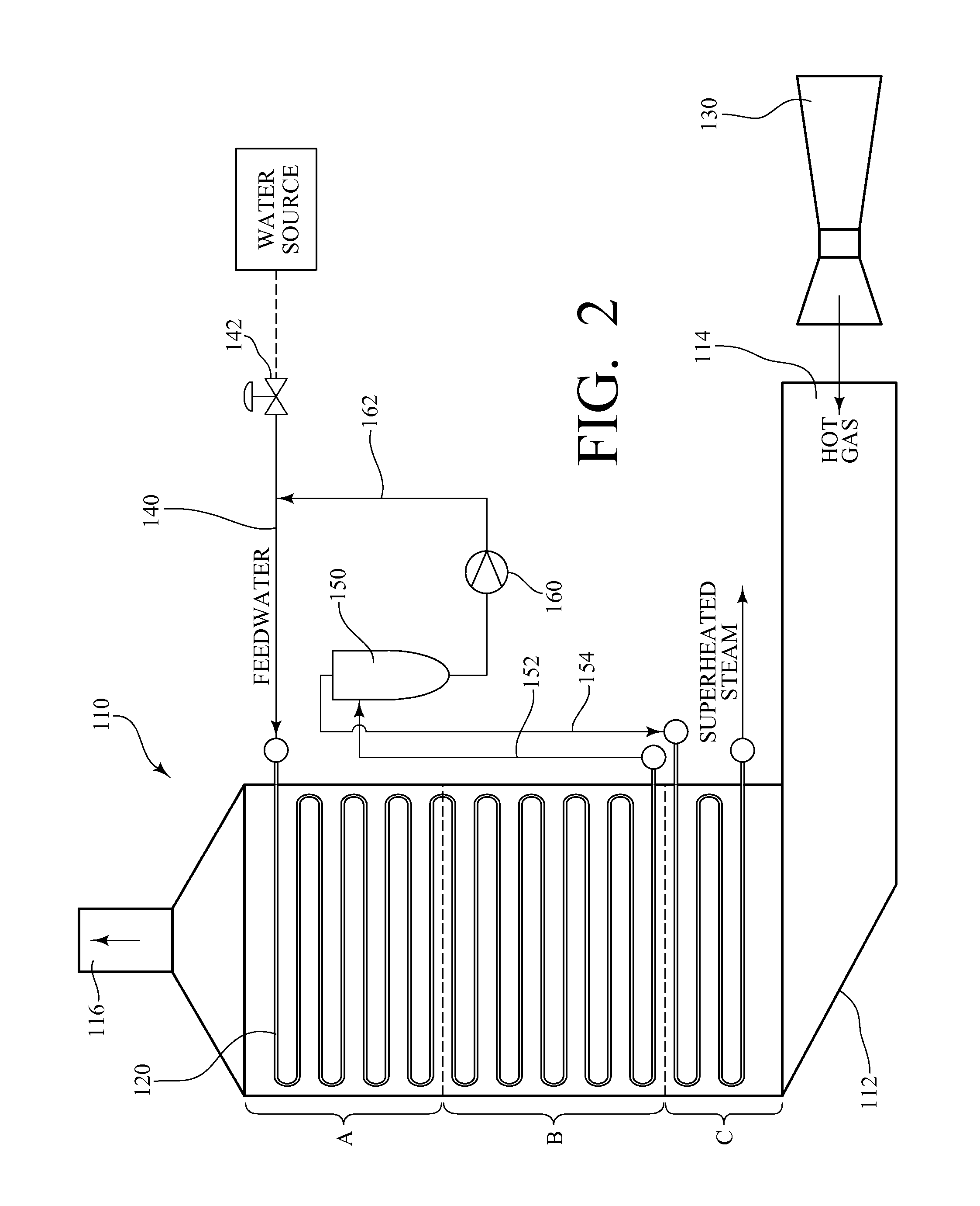
[0013]The present invention is a once-through steam generator (OTSG) that includes auxiliary components that facilitate a wet start-up and / or a dry start-up without suffering from the above-described disadvantages of prior art constructions.

[0014]Referring now to FIG. 2, an exemplary OTSG 110 made in accordance with the present invention includes a duct 112 having an inlet end 114 and a discharge end 116. The duct 112 is connected to a source 130 of a hot gas (in this case, hot flue gas from a combustion turbine), such that the hot gas flows from the inlet end 114 to the discharge end 116. A tube bundle120 is positioned in the duct 112. and essentially spans the height of the duct 112, with the heat transfer tubes of the tube bundle 120 in a horizontal orientation. Although each heat transfer tube of the tube bundle 120 defines a single continuous path through the duct 112, the tube bundle 120 can nonetheless be characterized as having: an economizer section (A), which is nearest th...


PUM


Abstract

A once-through steam generator comprises a duct having an inlet end in communication with a source of a hot gas; and a tube bundle installed in the duct and comprising multiple heat transfer tubes. The tube bundle has an economizer section, an evaporator section, and a superheater section. A steam separating device may be positioned between the evaporator section and the superheater section, wherein, as part of a wet start-up, hot water collected by the steam separating device is delivered from the steam separating device to mix with cold feedwater before it is introduced into the economizer section. A start-up module may be positioned in the duct near the inlet end, wherein, as part of a dry start-up, cold feedwater is delivered into the start-up module to generate hot water that is then mixed into the feedwater stream before it is introduced into the economizer section.

Description

CROSS-REFERENCE TO RELATED APPLICATIONS[0001]The present application claims priority to U.S. Provisional Patent Application Ser. No. 61 / 724,051 filed on Nov. 8, 2012, the entire disclosure of which is incorporated herein by reference.BACKGROUND OF THE INVENTION[0002]The present invention relates to once-through steam generators. A once-through steam generator (OTSG) is a heat recovery boiler that generates steam, primarily for use in power generation or for another industrial process. Traditional fossil fuel boilers, including heat recovery steam generators (HRSG), are commonly characterized as having three separate sections of heat transfer tubes, with a hot flue gas passing around such heat transfer tubes to generate steam. First, economizer sections heat condensate water, often close to the boiling point, but the water typically remains in a liquid phase. Second, evaporator sections convert the water heated in the economizer sections into saturated steam. Third, superheater secti...

Claims


Application Information

Patent Timeline
Patent Type & Authority Applications(United States)
IPC IPC(8): F22B29/06G05D11/02F22G1/02F22D1/12
CPCF22B29/06G05D11/02F22G1/02F22D1/12F22B37/26F22B37/32Y10T137/0329
Inventor STARK, DANIELTAYLOR, DARRYLTHOMPSON, ANTHONY A.PASHA, AKBERFLANNERY, KELLY M.
Owner VOGT POWER INT
Why Eureka
Try Eureka