
Snubber circuit for dc-dc voltage converter

a dc-dc voltage converter and resistor technology, applied in dc-dc conversion, climate sustainability, power conversion systems, etc., can solve the problems of high production costs and high unit costs, and achieve the effect of negligible power loss in this resistor and simple and cost-effective manner

Inactive Publication Date: 2014-05-08
ROBERT BOSCH GMBH
View PDF4 Cites 12 Cited by
  • Summary
  • Abstract
  • Description
  • Claims
  • Application Information

AI Technical Summary

Benefits of technology

The present invention provides a way to make a snubber circuit for a DC-DC voltage converter that is simpler and less expensive. This is done by replacing the inductive components in the circuit with a current-limiting resistor. This change results in negligible power loss and high efficiency. The technical effect is to improve the performance of the converter at a lower cost.

Problems solved by technology

The output capacitance of semiconductor switches which are turned off may result, in the case of electrically decoupled synchronous rectifiers, in the phenomenon of “secondary ringing”, that is to say the occurrence of unwanted oscillations of the current or voltage.
In particular, the inductive components such as snubber inductors which are usually used in buck converters are associated with high unit costs since the components themselves are expensive and also give rise to high production costs during mounting.

Method used


Image

  • Snubber circuit for dc-dc voltage converter
  • Snubber circuit for dc-dc voltage converter

Examples


Embodiment Construction

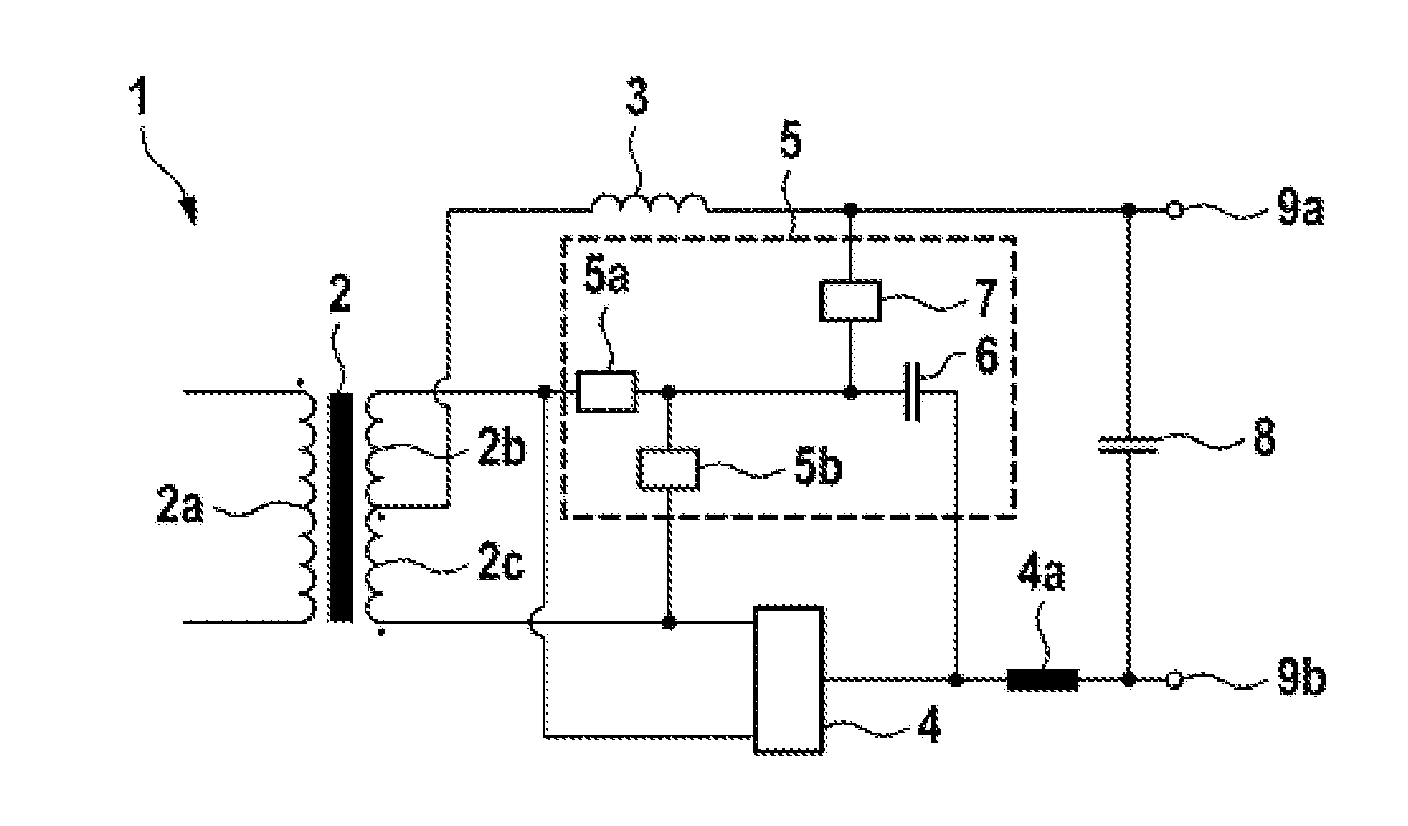
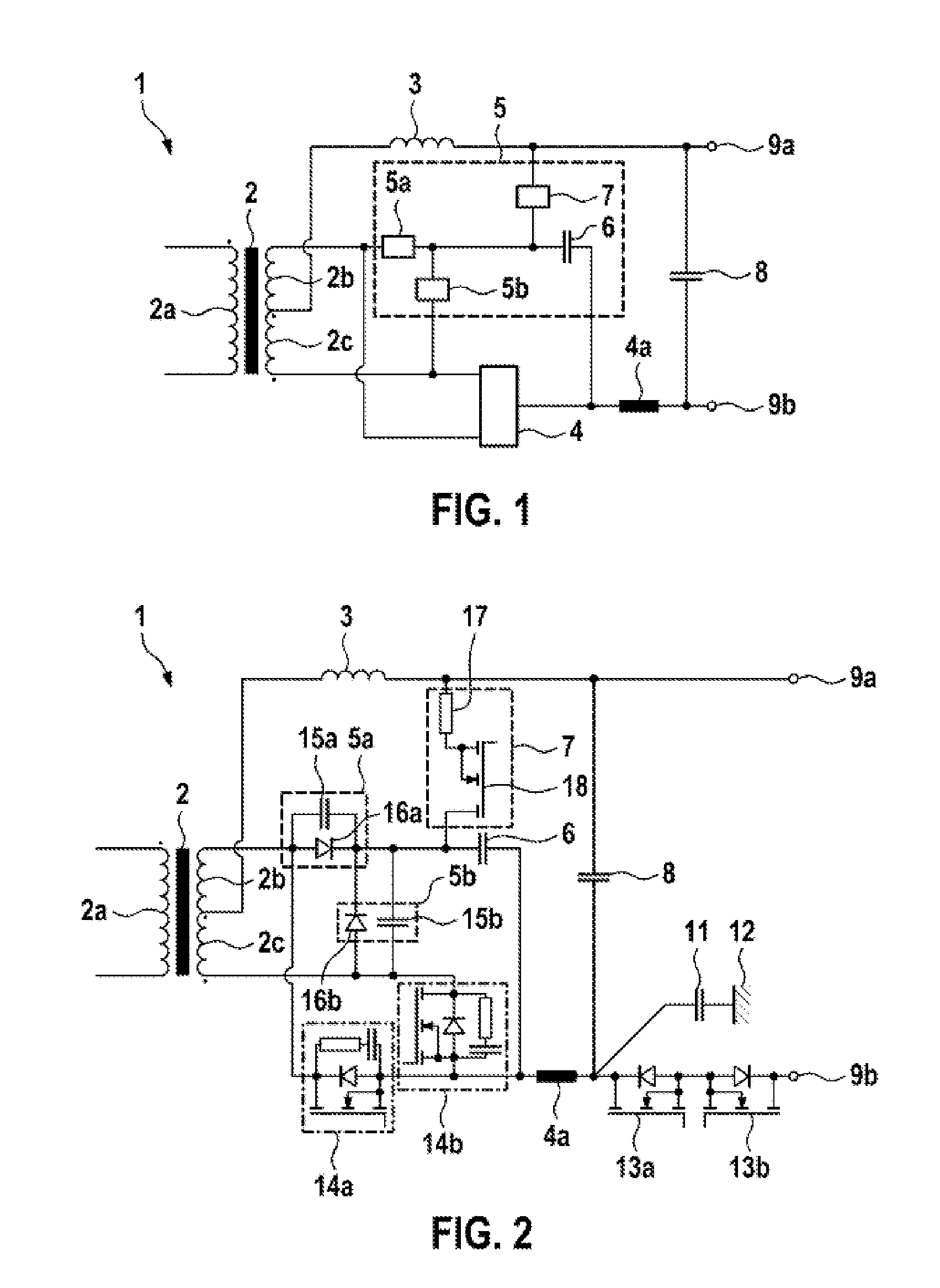
[0014]FIG. 1 shows a schematic illustration of a DC-DC voltage converter 1. The DC-DC voltage converter 1 comprises a transformer 2 with a primary winding 2a and a secondary winding which is divided into two sections 2b and 2c via a center tap. The transformer 2 may be designed, for example, to convert a high voltage into a low voltage and may have, for example, a winding ratio of the primary winding to the secondary winding of more than one, in particular 10:1, for example. The winding ratio of the two secondary winding sections 2b and 2c may not be equal to one. In particular, the winding ratio may be one in this case, that is to say the two secondary winding sections 2b and 2c have the same number of windings.

[0015]In this case, the center tap is connected to a first output connection 9a via a secondary-side inductance 3. The two terminal taps of the respective secondary winding sections 2b and 2c are connected, on the one hand, to two inputs of a synchronous rectifier circuit 4 ...


PUM


Abstract

The invention relates to a DC-DC voltage converter (1), having a transformer (2) having a primary winding (2a) and a secondary winding (2b, 2c) having a centre tap, an output inductor (3), which is connected to the centre tap and to a first output connection (9a), a synchronous rectifier circuit (4) having two synchronous rectifier switches (14a, 14b), each of which is connected to the terminal taps of the secondary winding (2b, 2c), and which are designed to produce a rectified output voltage on a second output connection (9b), and a snubber circuit (5) that is switched by means of the synchronous rectifier circuit (4). In this case, the snubber circuit has two diodes (16a, 16b), each of which is coupled to the terminal taps of the secondary winding (2b, 2c), a capacitor (6), which is coupled to the two diodes (16a, 16b) and which is designed to store resonant oscillation energy arising in the synchronous rectifier circuit (4), and a discharge circuit (7) comprising a series circuit containing a discharge switch (18) and a resistor (17), wherein the discharge circuit (7) is coupled between the first output connection (9a) and the capacitor and is designed to selectively feed back stored charge in the capacitor (6) to the first output connection (9a).

Description

BACKGROUND OF THE INVENTION [0001]The invention relates to a snubber circuit for a DC-DC voltage converter, in particular for a neutral point rectifier with synchronous rectification.[0002]Synchronous rectifier circuits are usually used for DC-DC voltage conversion, for example for the purpose of supplying a low-voltage electrical system of a vehicle. The power semiconductor switches, for example MOSFETs, used for this purpose currently have a lower voltage loss than diodes at relatively high direct currents, as a result of which the efficiency of the rectifier can be increased. The output capacitance of semiconductor switches which are turned off may result, in the case of electrically decoupled synchronous rectifiers, in the phenomenon of “secondary ringing”, that is to say the occurrence of unwanted oscillations of the current or voltage. In this case, resonance is effected between the leakage inductance of the secondary side of the transformer with the secondary-side inductance ...

Claims


Application Information

Patent Timeline
Patent Type & Authority Applications(United States)
IPC IPC(8): H02M3/335
CPCH02M3/33507H02M1/34H02M3/33592Y02B70/10
Inventor KOCH, STEFANTIAN, JIAN
Owner ROBERT BOSCH GMBH
Learn More