Resin-encapsulated current limiting reactor

a current limiting reactor and resin-encapsulated technology, applied in the direction of starter details, dynamo-electric converter control, magnetic bodies, etc., can solve the problems of requiring a large space for fault limiting reactors, affecting the characteristics and performance of motors, including load and electrical power systems, and damage to silicon controlled rectifiers, so as to ensure the electrical field and increase the accessibility. , the effect of easy installation

Inactive Publication Date: 2014-05-29
PHASETRONICS
View PDF16 Cites 5 Cited by
  • Summary
  • Abstract
  • Description
  • Claims
  • Application Information

AI Technical Summary

Benefits of technology

[0014]Once the windings are appropriately compiled, the windings are encapsulated in resin in order to create the reactor of the present invention. There are two main embodiments of the reactor: plastic molded case and mold casted. In either case, the windings are placed in a mold or plastic molded case and encapsulated in resin under vacuum. Because of this operation under vacuum, the resin-encapsulation fills all voids in the windings. Any gaps or separations between the layers of insulated copper and Nomex® fiber insulation will be filled by the resin. This creates superior mechanical support for reactor, which will be subjected to radial and tangential forces during the start of the motor. The resin-encapsulation also prevents deformation of the coil during the starting of the motor and increases the radial compressive strength of the reactor coil. The movement of the coils during motor starting conditions is therefore greatly suppressed. In addition, the resin-encapsulation prevents moisture penetration into windings. This prevents flashovers due to moisture condensation within windings.
[0018]The reactor of the present invention is preferably no larger than 9 inches by 15 inches by 15 inches, which is very small for this type of reactor. At the same time, the reactor of the present invention is dielectrically, thermally, and mechanically stronger than its non-resin-encapsulated counterparts. As mentioned above, the resin-encapsulated reactor of the present invention can withstand continuous voltage of 15 kV while taking up no more physical space than 9 inches by 15 inches by 15 inches. The non-resin-encapsulated reactor counterpart would need at least 5 inches more in each dimension so as to safely dissipate the electrical field created in the reactor during motor starting. The smaller space requirements of the resin-encapsulated reactor of the present invention allow it to be installed as a part of the switchgear. This makes installation easy and increases accessibility to the soft starter and the switchgear. The mechanical and thermal capability of resin-encapsulated reactor allow it to withstand 3.5 times the rated current of the induction motor for back-to-back switching periods of time, which are a maximum of 60 seconds. In short, not only is the resin-encapsulated reactor of the present invention smaller, capable of withstanding higher voltage and heat spikes, and able to be installed in the switchgear, but its inclusion within a soft starter makes the soft starter generally stronger and more reliable.

Problems solved by technology

The starting of induction motors is a process that can damage and influence characteristics and performances of the motor, including its loads and electrical power systems.
During the transient process, the “on” and “off” soft current rise, di / dt, may damage the Silicon Controlled Rectifiers (hereinafter, “SCRs”) as it passes them.
This fault limiting reactor would require a great deal of space in order to withstand high voltage levels.
As such, it could not be mounted in indoor metal clad switchgear or motor control centers.
This high voltage air core reactor is a standalone reactor that cannot be used to support any other equipment and also cannot be mounted in switchgear or motor control centers.
This current limiting electrical reactor cannot be used in medium voltage soft starters for several reasons.
First, the reactor does not satisfy dielectric requirements for the motor control centers and medium voltage switchgear.
Second, the reactor cannot be mounted in a space limited environment for use as support for heat sinks of SCRs.
This current limiting reactor is built for outdoor applications and requires a great deal of space.
This is a complex current limiting device that requires a tremendous amount of space.
In addition, it cannot be used for current limiting of fast transients, such as the one experienced with medium voltage soft starters.

Method used


Image

  • Resin-encapsulated current limiting reactor
  • Resin-encapsulated current limiting reactor
  • Resin-encapsulated current limiting reactor

Examples


Embodiment Construction

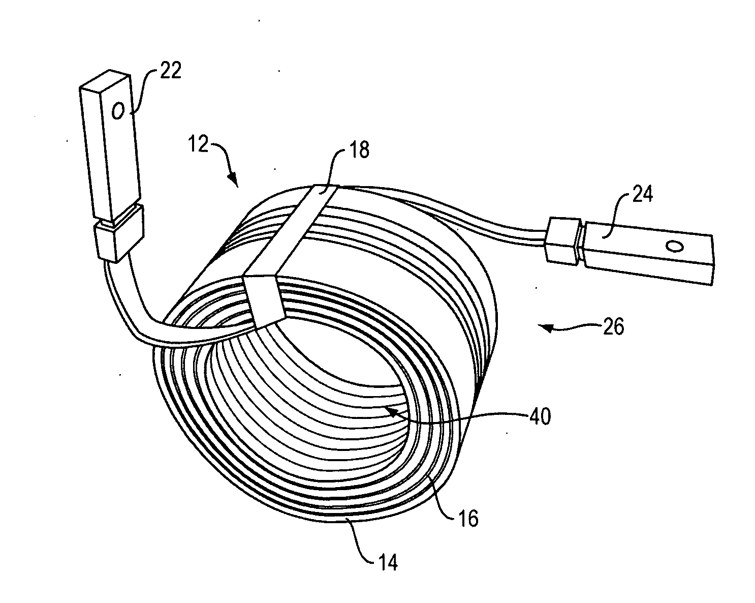
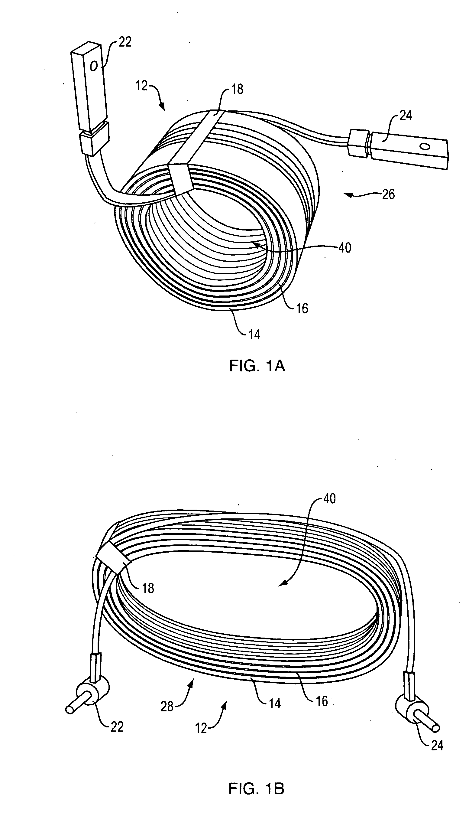
[0046]Referring first to FIGS. 1A-1B, windings 12 are shown before resin-encapsulation. FIG. 1A shows circular 26 windings. FIG. 1B shows elliptical 28 windings. In each, the preferred layers of copper insulated conductors 14 are visible alternating with layers of interlayer insulation 16. It is understood that copper insulated conductors 14 may be substituted by other conductors, such as aluminum, or a combination of aluminum and copper. Moreover, the cross sections of the conductors within the insulated conductors 14, which are not visible in these views, may have cross sections of any shape, but are preferably round, square, or rectangular. The insulation around the conductors may be any art-recognized insulator commonly used for insulating conductors, such as plastic or PVC. Finally, although the preferred interlayer insulation 16 is Nomex® fiber, Nomex® fiber may be substituted by any meta-aramid with similar heat resistance and strength characteristics. Windings 12 are prefera...


PUM

PropertyMeasurementUnit
inductanceaaaaaaaaaa
rated voltageaaaaaaaaaa

Abstract

The present invention is a resin-encapsulated current limiting reactor that has a number of layers of insulated copper with terminals on each end, and a number of layers of Nomex® fiber insulation wrapped adjacent to each other into a circular or elliptical shape, and encapsulated in polyurethane resin under vacuum.

Description

CLAIM OF PRIORITY[0001]This application is a continuation in part and claims the benefit of priority of co-pending U.S. Non-Provisional patent application Ser. No. 13 / 455,947, filed on Apr. 25, 2012.FIELD OF THE INVENTION[0002]The present invention relates to current limiting reactors, and in particular, to an improved current limiting reactor with space saving dielectric properties for use in medium voltage soft starters for induction motors.BACKGROUND[0003]The starting of induction motors is a process that can damage and influence characteristics and performances of the motor, including its loads and electrical power systems. A significantly higher starting current than the rated current may create mechanical and thermal stress on the motor and the loads. Large voltage fluctuations, such as dips and sags, may occur in the electrical power system associated with the motor.[0004]The invention disclosed in the present inventor's co-pending application Ser. No. 13 / 455,947 is a soft st...

Claims


Application Information

Patent Timeline
Patent Type & Authority Applications(United States)
IPC IPC(8): H01F5/06H01F41/12H02P1/02
CPCH01F5/06H01F27/327H01F41/127H02P1/02H02P1/26H02P1/423Y10T29/49071
Inventor DAMJANOVIC, ALEKSANDAR B.
Owner PHASETRONICS
Why Eureka
Try Eureka