Subject information obtaining apparatus and subject information obtaining method

a subject information and obtaining apparatus technology, applied in the field of subject information obtaining apparatus and subject information obtaining methods, can solve the problem of not obtaining the effect of improving the snr, and achieve the effect of shortening the reception signal obtaining period and improving the snr

Inactive Publication Date: 2014-06-05
CANON KK
View PDF9 Cites 6 Cited by
  • Summary
  • Abstract
  • Description
  • Claims
  • Application Information

AI Technical Summary

Benefits of technology

[0010]According to the aspect of the present invention, it is possible to improve the SNR by increasing the number of times when the reception signal is obtained, and further, it is possible to shorten the reception signal obtaining period.

Problems solved by technology

As a result, an effect of the improvement in the SNR is not obtained.

Method used


Image

  • Subject information obtaining apparatus and subject information obtaining method
  • Subject information obtaining apparatus and subject information obtaining method
  • Subject information obtaining apparatus and subject information obtaining method

Examples


first exemplary embodiment

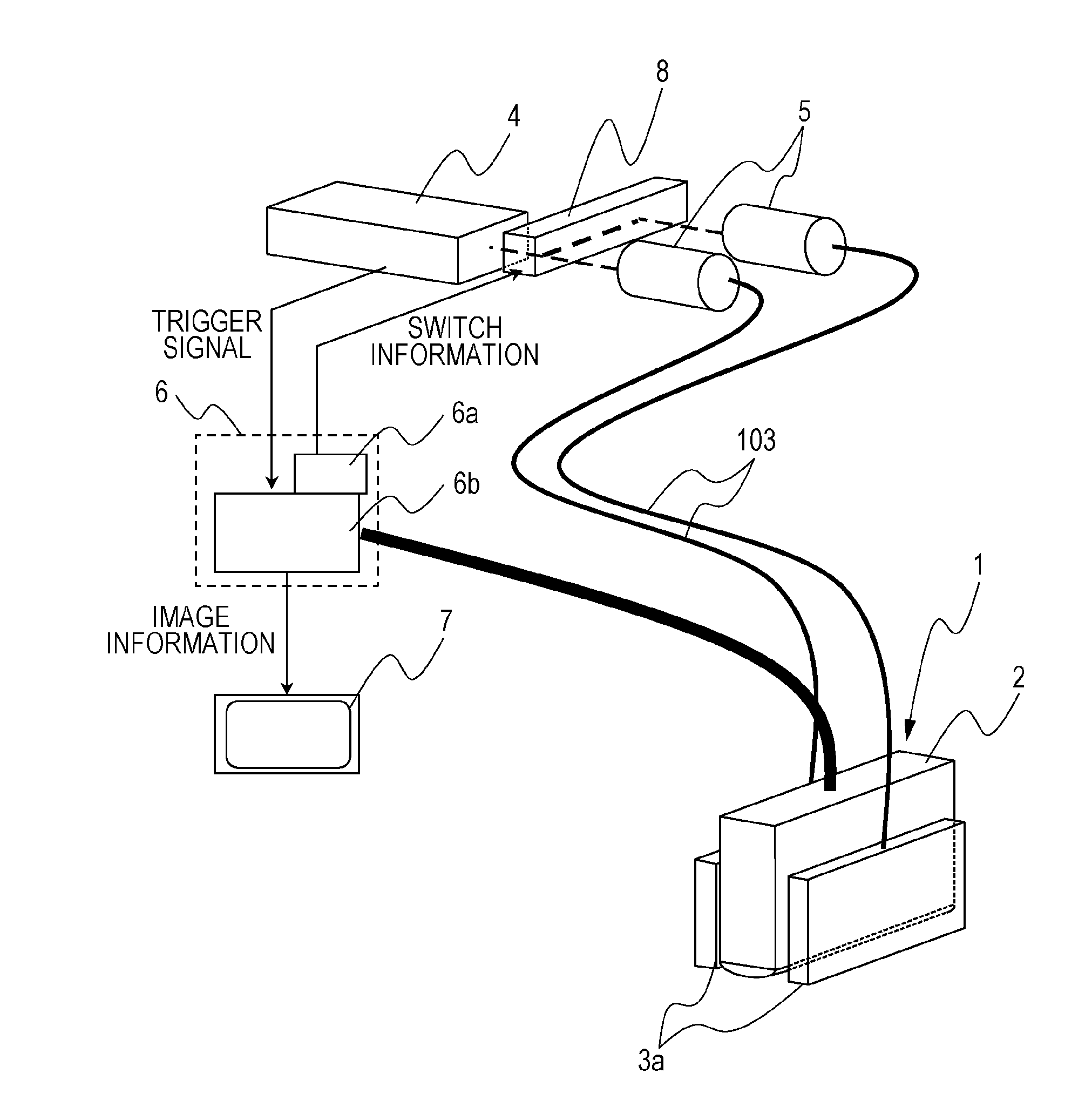
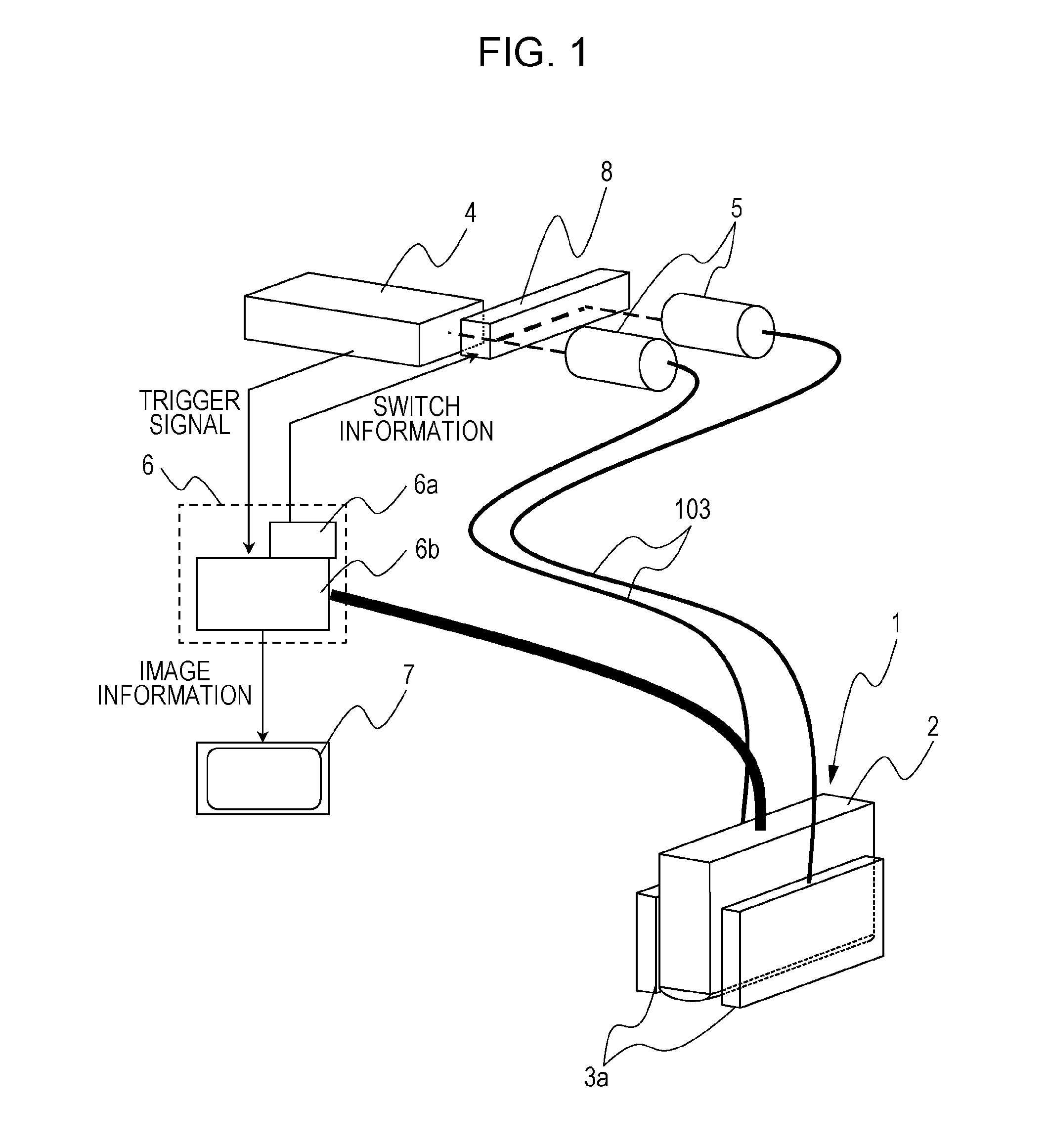
[0023]A photoacoustic apparatus that is a subject information obtaining apparatus according to a first exemplary embodiment will be described by using FIG. 1. The subject information obtaining apparatus according to the exemplary embodiment of the present invention is at least provided with a light source 4, a photoacoustic probe 1, and a processing apparatus 6.

[0024]The light source 4 generates pulsed light of near-infrared ray or the like. For the light source 4, a laser with which a large output can be obtained is preferably used, but a light emitting diode or the like can also be used instead of the laser. Preferably, an Nd:YAG laser, an alexandrite laser, or a Ti:sa laser or an OPO laser using an Nd:YAG laser beam as exciting light is used. In addition to the above, various lasers such as a solid laser, a gas laser, a dye laser, and a semiconductor laser can be used as the laser. For a wavelength of the generated light, a particular wavelength may be selected depending on a com...

second exemplary embodiment

[0048]According to the first exemplary embodiment, the mode has been described in which the outgoing terminals 3a of the bundle fiber are provided one by one at the positions corresponding to the illumination areas of the pulsed light while sandwiching the receiver 2, and the illumination is carried out alternately. According to a second exemplary embodiment, a mode will be described in which still more outgoing terminals functioning as the irradiation units are provided. A configuration other than the number of the optical paths for the pulsed light from the light source and the structure of the photoacoustic probe is the same as the first exemplary embodiment, and a description thereof will be omitted.

[0049]FIG. 5A is a schematic diagram of the photoacoustic probe 1 as seen from the lateral side direction according to the present embodiment. The photoacoustic probe 1 is provided with four outgoing terminals 3a (a first irradiation unit, a second irradiation unit, a third irradiati...

third exemplary embodiment

[0057]According to the first exemplary embodiment and the second exemplary embodiment, the mode has been described in which the outgoing terminals 3a of the bundle fibers functioning as the irradiation units of the pulsed light are provided so as to sandwich the receiver 2. According to a third exemplary embodiment, a mode will be described in which the outgoing terminals 3a of the plural bundle fibers are provided on one lateral face side of the receiver 2. As an example, in FIG. 6, the two outgoing terminals 3a of the bundle fibers are both provided on one side of the receiver 2. It is noted that the basis apparatus configuration and the method for the averaging or integrating processing of the mutual reception signals or the combining processing of the mutual pieces of image data have been described in the first exemplary embodiment and the second exemplary embodiment, and a description thereof will be omitted.

[0058]In FIG. 6, as described in the second exemplary embodiment, the ...


PUM


Abstract

A subject information obtaining apparatus includes a probe including a receiver that receives an acoustic wave to be converted to an electric signal and first and second irradiation units that irradiate mutually different areas on a subject surface with pulsed light, a control unit that controls illumination positions of the pulsed light to avoid continuous irradiation of the subject with the pulsed light from the first and second irradiation units, and a signal processing unit that performs averaging or integrating of electric signals derived from the pulsed light illuminated from the first and second irradiation units and obtains a characteristic distribution in the subject by using the averaged or integrated signal or performs combining of distributions obtained by using electric signals derived from the pulsed light illuminated from the first and second irradiation units and obtains a combined distribution as the characteristic distribution in the subject.

Description

TECHNICAL FIELD[0001]The present invention relates to a subject information obtaining apparatus and a subject information obtaining method. In particular, the invention relates to a subject information obtaining apparatus that irradiates a subject with pulsed light and receives an acoustic wave generated in the subject to obtain internal subject information and a subject information obtaining method.BACKGROUND ART[0002]A photoacoustic imaging such as a photoacoustic tomography (hereinafter, which will be referred to as PAT) attracts attention as a method of specifically imaging a generated vascularization caused by cancer. The PAT is a technology of illuminating pulsed light (near-infrared ray or the like) on a subject such as a living body and receiving a photoacoustic wave generated from the inside of the living body to carry out imaging.[0003]NPL 1 discloses a hand-held type apparatus using the photoacoustic imaging technology. FIG. 7A illustrates a schematic diagram of the hand-...

Claims


Application Information

Patent Timeline
Patent Type & Authority Applications(United States)
IPC IPC(8): A61B5/00
CPCA61B5/0095A61B5/0073A61B5/7203A61B5/7242A61B2560/0425G01N21/1702G01N29/2418G01N2021/1706
Inventor TOKITA, TOSHINOBU
Owner CANON KK
Why Eureka
Try Eureka