
DNA chip with micro-channel for DNA analysis

a micro-channel and dna technology, applied in the field of dna chip with micro-channel, can solve the problems of high unit price of material in comparison with plastic, difficult to realize a device with micro-channel which can meet all the above requirements, and high thermal conductivity of material, etc., to achieve rapid and convenient operation, increase and decrease the temperature

Active Publication Date: 2014-07-03
INTERUNIVERSITAIR MICRO ELECTRONICS CENT (IMEC VZW)
View PDF2 Cites 6 Cited by
  • Summary
  • Abstract
  • Description
  • Claims
  • Application Information

AI Technical Summary

Benefits of technology

The present patent describes a DNA chip that can quickly and conveniently extract and amplify DNA, as well as detect specific sequences. The chip is highly versatile and can be used for a variety of applications, such as genome analysis and blood testing. The chip's unique structure allows for high-speed temperature control and manipulation of analytes and reagents, making the DNA analysis process more efficient and easy. Overall, the DNA chip provides a useful and convenient tool for conducting DNA analysis.

Problems solved by technology

However, due to limitations on the nature of a material of a substrate that forms a chip with micro-channel, it is difficult to realize a device with micro-channel which can meet all the foregoing requirements.
On the other hand, however, the plastic substrate has a problem that it is not suitable for formation of a fine filter structure for separating impurities such as blood cells and for formation of a thermal reactor for which it is required to increase and decrease the temperature at a high speed, such as a PCR (polymerase chain reaction), because it is difficult to process fine structures in a sub-micrometer order and the thermal conductivity of the material is not satisfactory.
On the other hand, however, there is the problem that the unit price of the material is high in comparison with plastic, and the silicon substrate is not suitable for storage of a reagent because affinity between the surface of silicon and a biological / bio material is not necessarily high, and therefore non-specific adsorption of a protein and DNA occurs.
As described above, plastic and silicon have mutually contradictory advantages and disadvantages, and with a configuration using a substrate of only one of silicon and plastic, conditions required for a chip with micro-channel for used in DNA analysis cannot be adequately satisfied.
In this method, however, the temperature cannot be increased and decreased at a high speed because a thermal reactor is formed of a plastic material, and also the reactor is isolated from silicon as a heating surface with a glass substrate interposed therebetween, so that it is very difficult to secure a thermal contact, leading to poor heat conduction.
Further, the method cannot be used conveniently because it employs a structure in which an analyte and a reagent are supplied from outside the chip.
Therefore, the method has the problem that it is not suitable for quick and convenient treatments.
However, in this method, a sensor is confined to a DNA micro-array chip, and this is formed on a silicon substrate identical to that of the thermal reactor (PCR).
That is, steps of producing the thermal reactor and the sensor should be successively performed, and the design cannot be flexibly changed according to an intended purpose.
Further, only one thermal reactor is mounted, and only a refined genome can be used as an analyte, so that a treatment from blood cannot be performed.
The method cannot adapt to applications that require two stages of PCRs: a PCR intended for extracting a genome to be analyzed from blood and a PCR intended for selectively amplifying DNA based on presence / absence of a SNP in the object to be analyzed.
That is, the method has the problem that it cannot adapt to applications of detection from blood, and is therefore poor in versatility.

Method used


Image

  • DNA chip with micro-channel for DNA analysis
  • DNA chip with micro-channel for DNA analysis
  • DNA chip with micro-channel for DNA analysis

Examples


embodiment 1

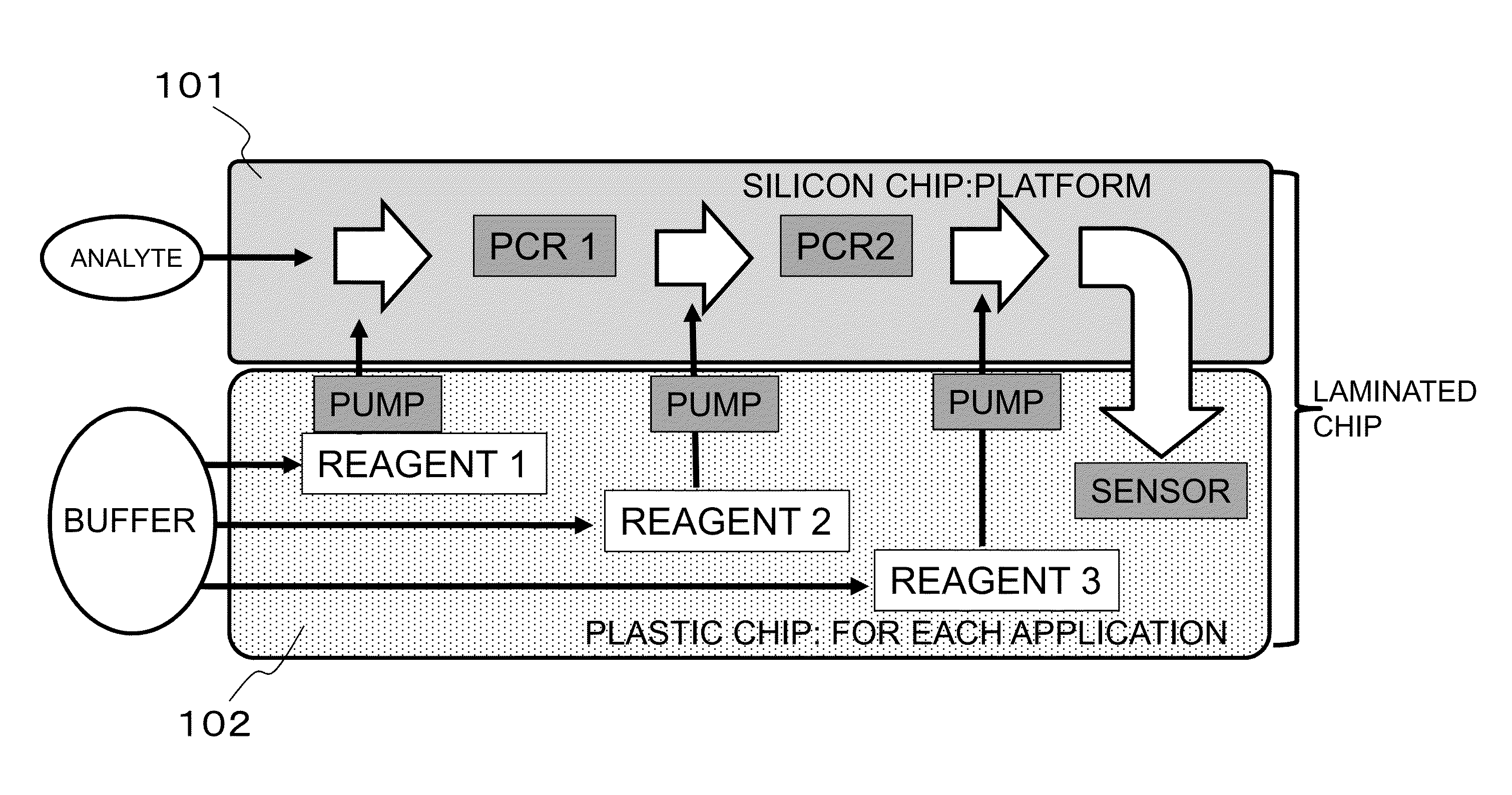
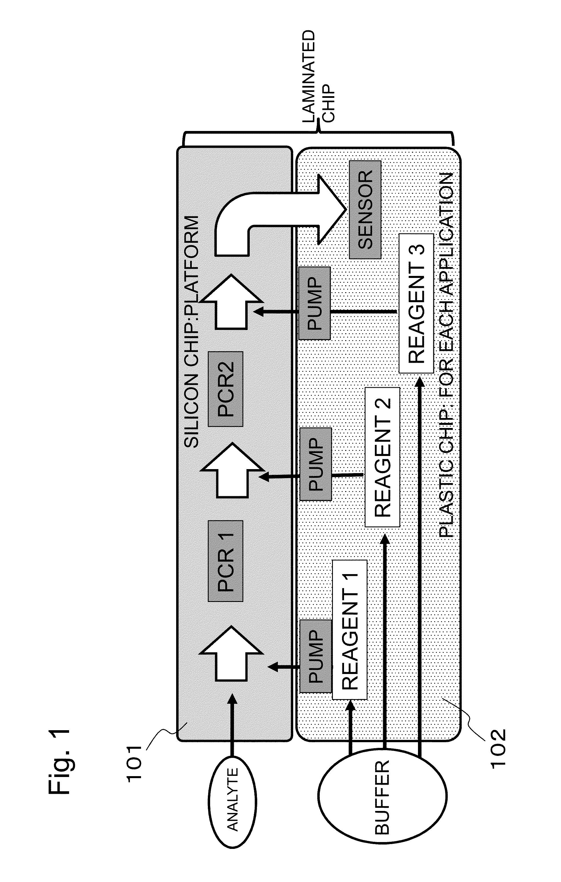
[0112]FIG. 1 is a general conceptual view of a chip with micro-channel according to the present disclosure. The DNA chip with micro-channel for DNA analysis in the present disclosure has a structure in which a silicon layer 101 (chip A) and a plastic layer 102 (chip B) are laminated. The chip A includes at least two PCR reactors connected in series in a micro-channel, and at least one filter including a plurality of silicon pillars between the PCR reactors, the chip B includes a reagent, a liquid delivery mechanism and a sensor in a micro-channel, and the reagent, liquid delivery mechanism and sensor can be changed according to a kind of an analyte and an object to be detected. Throw of an analyte and a reagent and treatments proceed in order along the arrow in FIG. 1.

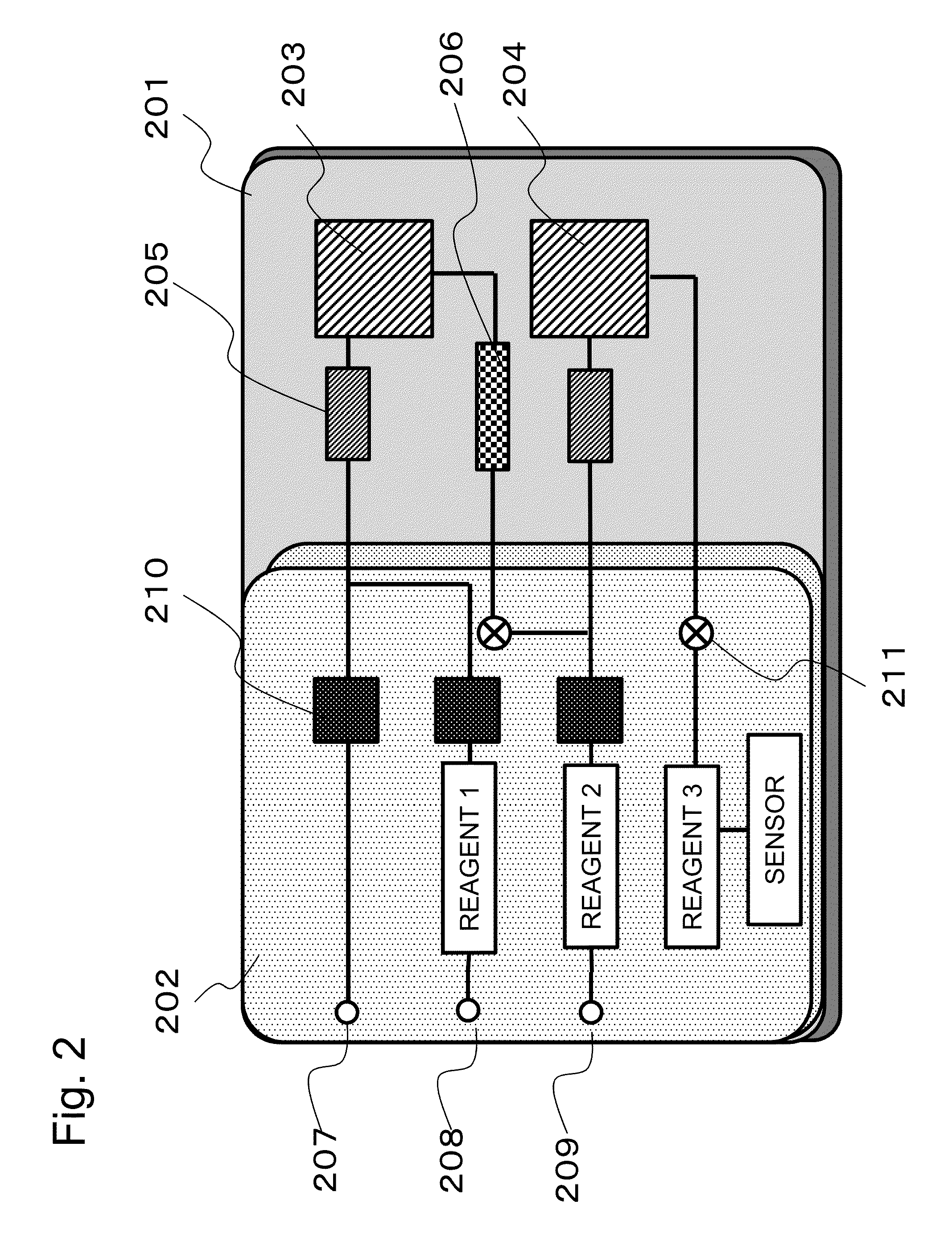
[0113]FIG. 2 is a schematic view showing components of the DNA chip with micro-channel for DNA analysis according to the present disclosure. The material of the chip A is silicon, a channel and a structure are engraved...

example 1

[0132]A desired DNA fraction including the 114th base of the 12th exon of an acetaldehyde dehydrogenase 2 (ALDH 2) gene was extracted and amplified from a human genome analyte by using a DNA chip with micro-channel for DNA analysis according to one embodiment of the present disclosure. A DNA fragment with a fraction length of 141 bp was extracted and amplified with the aforementioned Primer 1 and Primer 2 used as primers.

[0133]The reagent (A) as a reagent 1 was mixed with an analyte in a mixer, and then reaction in a PCR 1 reactor was carried out in 30 cycles of PCR under conditions of 98° C. for 30 seconds, 60° C. for 30 seconds and 68° C. for 30 seconds. Subsequently, the reaction product was made to pass through a filter and a PCR 2 as it was. Three μL of this sample was collected. Subsequently, existence or nonexistence of DNA amplification was checked using an electrophoresis method with agarose gel. The second lane in FIG. 9 corresponds to the result for existence or nonexiste...

example 2

[0134]DNA was amplified from a blood analyte by using a DNA chip with micro-channel for DNA analysis according to one embodiment of the present disclosure. As a model of DNA amplification, blood of each of types AB and O was used as a template. A DNA fragment including the 261st base of the sixth exon in a genome in human blood was extracted and amplified. A DNA fragment with a fraction length of 134 or 135 bp was extracted and amplified with the aforementioned Primer 3 and Primer 4 used as primers.

[0135]The reagent (B) as a reagent 1 was mixed with an analyte in a mixer, and then reaction in a PCR 1 reactor was carried out in 35 cycles of PCR under conditions of 98° C. for 30 seconds, 60° C. for 30 seconds and 68° C. for 30 seconds. Subsequently, the reaction product was made to pass through a filter, and unnecessary blood components fractioned in the PCR reactor were removed. The reaction product was made to pass through a PCR 2 reactor as it was, three μL of this sample solution ...


PUM

PropertyMeasurementUnit
thicknessaaaaaaaaaa
depthaaaaaaaaaa
voltageaaaaaaaaaa

Abstract

Provided is a DNA chip with micro-channel for DNA analysis, which has a structure in which a silicon layer (chip A) and a plastic layer (chip B) are laminated, wherein the chip A includes at least two PCR reactors connected in series in a micro-channel, and a filter between the PCR reactors, the chip B includes a reagent, a liquid delivery mechanism and a sensor in a micro-channel, and the reagent, liquid delivery mechanism and sensor can be changed according to a kind of an analyte and an object to be detected.

Description

CROSS-REFERENCE TO RELATED APPLICATIONS[0001]This is a continuation application of International Application No. PCT / JP2013 / 062310, with an international filing date of Apr. 19, 2013, which claims priority of Japanese Patent Application No. 2012-96885 filed on Apr. 20, 2012, the contents of which is incorporated herein by reference.BACKGROUND[0002]1. Technical Field[0003]The present disclosure relates to a chip with micro-channel which is formed on a laminated substrate of silicon and plastic. More particularly, the present disclosure relates to a chip with micro-channel which integrally has functionalities for quickly and conveniently extracting and amplifying desired DNA from an analyte containing a gene, or detecting a sequence of the DNA.[0004]2. Related Art[0005]In recent years, progress of genetic diversity analysis and expression analysis has been outstanding owing to improvement of DNA analysis techniques. Particularly in medical fields, the relationship between diseases and...

Claims


Application Information

Patent Timeline
Patent Type & Authority Applications(United States)
IPC IPC(8): C12Q1/68
CPCC12Q1/686B01L3/502707B01L3/502715B01L7/52B01L2300/0636B01L2300/0681B01L2300/0816B01L2300/0861B01L2300/0883B01L2400/086C12Q2565/629
Inventor TANAKA, HIROYUKIHIRAOKA, MAKIJONES, BENJAMINFIORINI, PAOLO
Owner INTERUNIVERSITAIR MICRO ELECTRONICS CENT (IMEC VZW)
Learn More