Multilayer filter

Inactive Publication Date: 2014-08-14
NANYANG TECH UNIV
View PDF2 Cites 11 Cited by
  • Summary
  • Abstract
  • Description
  • Claims
  • Application Information

AI Technical Summary

Benefits of technology

This patent describes a multilayer filter that has a first layer with many small openings and a second layer that sits on top of the first layer and reduces the size of the openings. The second layer is designed to partition the openings, making them smaller. The filter can be made by fabricating a configuration in the second layer that reduces the size of the openings. When the layers are released from the substrate, the multilayer filter is created. This invention has technical effects such as reducing the size of the openings in the filter and improving its performance.

Problems solved by technology

Available bio-sensors only detect microorganisms which are directly in contact with the sensitive region; hence, detection of low concentration bacteria in a large volume is hard because there is low possibility for bacteria to interact with the sensitive zone of biosensor [2].
Negative features of commercial filters like rough surface, tortuous pore path, low pore density and high coefficient of variation [4] (CV>20%) are the major factors which compromise their efficiency and throughput during microfiltration.
The best homogeneity in terms of pore size distribution and pore shape in commercial membranes is possessed by the track-etched polymeric membranes (normally polycarbonate) by cylindrical pores, but the irregular array of pores on the surface, low porosity and also their angle with the surface limits the strength, flow rate and reliability of them in repeated process-scale.
Identical and uniform pore diameter and smooth surface allow the filtration membrane to have low transmembrane pressures and large flux, but the restriction in membrane material (limited to nitride) and small thickness of the silicon nitride film (<1 μm), which allows only low working pressure (<2 bar) limits the application of this type of filtration membrane [6,7].
A major impediment in fabrication of membrane with this method is the demoulding of cured membrane, because peeling off of the membrane from the mould often results in membrane damage and failure.
Furthermore, the choices of pore size and pore density are restricted due to the use of alumina templates.
In this method, aperture array lithography and reactive ion etching (RIE) techniques have been combined to obtain polymeric membranes with a homogeneous pore diameter on the scale of hundreds of nanometers, but it is a costly process which is not appropriate for large-scale production.
In spite of capability of this method in employing a variety of polymers for filter design, some major problems such as enlargement of pore size during the shrinkage stage, fragility of the mould and folding (or failure) of membrane during the release stage are associated with this method.
In all the aforementioned methods, it is difficult or perhaps even impossible to make a membrane with small features (i.e. down to hundreds of nanometer) without compromising the membrane strength.
Hence, in order to obtain membrane with pore size of around 1 μm or less, the membrane thickness would be smaller than 2 μm which is so fragile that it cannot be used for microfiltration applications.
Technically, fabrication of small perforations (e.g. 0.1-5 μm) inside a thick photoresist film (e.g. SU-8) is difficult due to the tapering effect, which normally happens during UV exposure (i.e. usually, the top layer is overexposed and tends to be wider than the bottom layer which is relatively underexposed, resulting in variation in the lateral dimensions).

Method used


Image

  • Multilayer filter
  • Multilayer filter
  • Multilayer filter

Examples


example 1

Method of Preparing the Filter

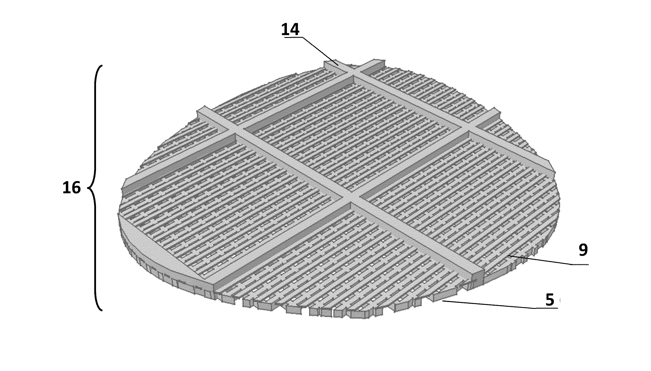
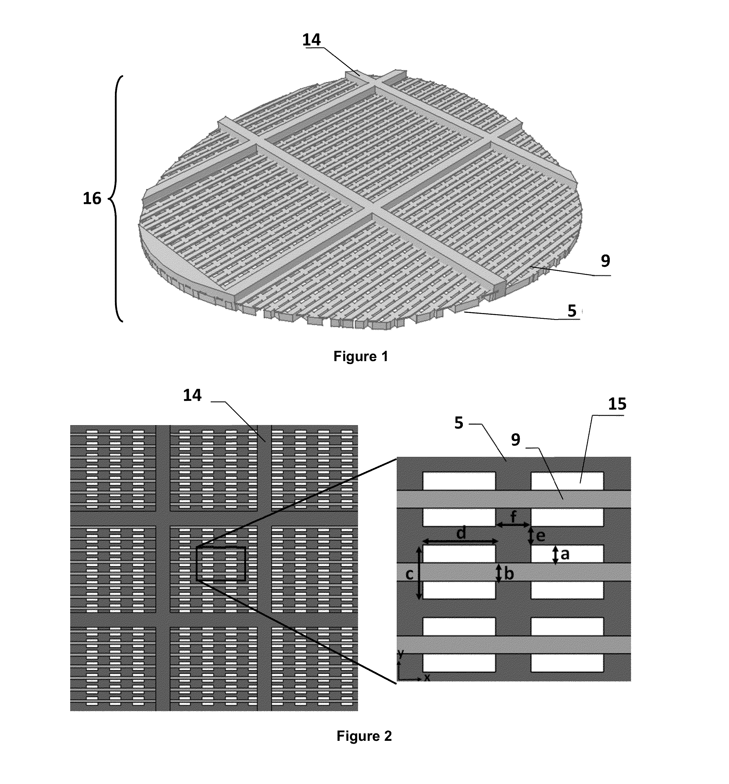
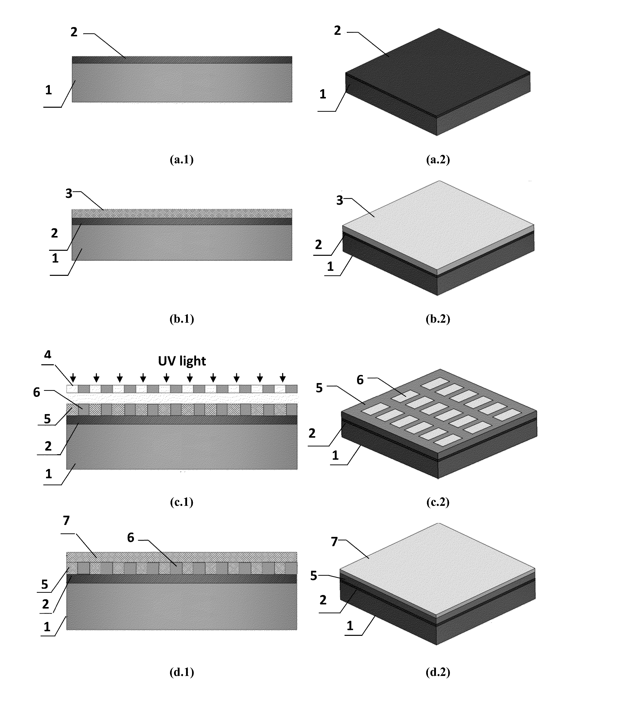
[0079]As an example, the method of preparing the multilayer membrane itself is described below. FIG. 1 shows a cut-view of multilayer polymeric membrane schematically, generally at 16, embodying the present invention. In accordance with the present invention, micro / nano-filter membrane includes at least a filter layer that comprises an array of mono-sized pores, and a support layer that includes a precision-shaped support structure (FIG. 2). FIG. 3 also shows the schematic cross-sectional (a.1 to i.1) and 3-D (a.2 to i.2) view of the fabrication process in details. For the purpose of illustration, the filter membrane as shown in FIG. 2 is not to scale. Although, theoretically, the support layer could have a thickness in order of membrane thickness, more typically the filter layer will be substantially thinner than the support structure. In the present invention, the filter layer thickness can be between 0.05-500 μm while the support structure has the th...

example 2

Applications of the Filter

[0100](a) Isolation of C. parvum oocysts

[0101]The capturing capability of the multilayer polymeric filter was verified by a two-step C. parvum oocysts filtration method. In the first step, 10 L of the sample, which was pure water (collected from a Millipore purification unit (MilliQ plus)) spiked with 2×10³ heat inactivated C. parvum oocysts (Waterborne Inc. New Orleans, La., USA, Cat No: P102C@1×10⁶) was filtered using a multilayer polymeric micro-sieve. The filtration was performed in dead-end mode using a peristaltic pump at a flow rate of 2 L min−1. The schematic representation of the filtration process and also experimental setup is illustrated in FIGS. 8 and 9, respectively. Upon completion of filtration, containers were rinsed with 2 litres of pure water that were additionally filtered. Then the filtered water goes to a subsequent filtration step using an Anodisc membrane (Whatman, Cat No: 6809-5522) with nominal pore size of 0.2 μm to capture any oo...


PUM

PropertyMeasurementUnit
Lengthaaaaaaaaaa
Sizeaaaaaaaaaa
Permeabilityaaaaaaaaaa

Abstract

This invention relates to a multilayer filter. The filter comprises at least a first layer comprising a plurality of openings and at least a second permeable layer overlaying the first layer and reducing the size of the openings. The filter may further comprise one or more successive layers overlaying the second layer, wherein each layer further successively reduces the size of the openings. The filter may be used for separation of particles from fluid or gas. There is also provided a method for fabricating a multilayer filter.

Description

CROSS-REFERENCE TO RELATED APPLICATIONS[0001]The present application is a National Stage application of International Application No. PCT / SG2012 / 000343. International Application No. PCT / SG2012 / 000343 was filed in the Intellectual Property Office of Singapore within one-year of and claims priority to Singapore Application No. 201106927-5. Accordingly, this application is a filing under 35 U.S.C. 371 as the National Stage of International Application No. PCT / SG2012 / 000343, filed Sep. 20, 2012, entitled “A MULTILAYER FILTER,” by Majid EBRAHIMI WARKIANI, et al., and claims foreign priority under 35 U.S.C. 119 to Singapore Patent Application No. 201106927-5, filed with the Intellectual Property Office of Singapore on Sep. 21, 2011 and entitled “A MULTILAYER FILTER”, by Majid EBRAHIMI WARKIANI, et al., each of which are incorporated herein by reference in their entirety for all purposes.FIELD OF THE INVENTION[0002]The present invention relates to a multilayer filter and methods for fabri...

Claims


Application Information

Patent Timeline
IPC IPC(8): B01D29/05B01D46/10
CPCB01D46/10B01D29/05B01D67/0034B01D67/0062B01D2325/021B01D39/083B01D2239/065B01D2239/1216Y10T29/49826
Inventor EBRAHIMI WARKIANI, MAJIDGONG, HAIQING
Owner NANYANG TECH UNIV
Why Eureka
Try Eureka