Implantable shunt system and associated pressure sensors

a technology of pressure sensor and implantable shunt, which is applied in the field of implantable shunt system and associated pressure sensor, can solve the problems of increased intracranial pressure inside the skull, progressive enlargement of the head, convulsion, tunnel vision, etc., and achieve the effect of relieving overpressur

Active Publication Date: 2014-08-28
ALFRED E MANN FOUND FOR SCI RES
View PDF12 Cites 33 Cited by
  • Summary
  • Abstract
  • Description
  • Claims
  • Application Information

AI Technical Summary

Benefits of technology

[0009]An exemplary embodiment of the invention includes the use of three pressure sensor modules disposed within a shunt that includes a fluid flow control valve. This configuration finds critical use in the treatment of hydrocephalus where it is imperative to extract excessive fluids from a patient's cranium to relieve overpressure that causes pain, improper brain functions and other tragic effects of the condition such as, permanent brain damage. The use of three pressure sensors, strategically positioned in the shunt, provides critical and reliable information regarding the overall condition of the shunt and whether the shunt is plugged, the location of the plugged portion of the shunt if that is the case and whether the valve is malfunctioning.

Problems solved by technology

This may cause increased intracranial pressure inside the skull and progressive enlargement of the head, convulsion, tunnel vision, and mental disability.
Hydrocephalus can also cause death.
However, pressure sensors must have certain attributes in order to be effective in long term (greater than four weeks) pressure monitoring applications and because today no devices are commercially available that have all the necessary attributes, hydrocephalus and TBI are treated without the benefit of continuous, long term intracranial pressure information.
Accordingly, the shortcomings of current devices creates a severe limitation in monitoring the effectiveness of ventriculoperitoneal shunts, which are commonly used in treating hydrocephalus and in treating acute brain injury.
In such instances an additional concern is the replacement of short term sensors that have failed with the attendant risk of infection accompanying sensor use.
Since the catheter is compliant, the transmission of accurate and reliable pressure values is undependable.
The system described in Ko also suffers from the same disadvantages as those devices in the art using fluid filled catheters in that the accuracy and reliability of pressure measurements remain undependable.
The device of Orth, is severely limited in its application since it is not implantable because the housing is not sealed and cannot be made hermetic due to the use and orientation of the O-ring.
The long term reliability and accuracy of the pressure measurements of the disclosed transducer remains a question, at least, because of the involved mechanical arrangement of the bellows and the coaxially variable components will experience hysteresis and materials fatigue causing calibration drift.

Method used


Image

  • Implantable shunt system and associated pressure sensors
  • Implantable shunt system and associated pressure sensors
  • Implantable shunt system and associated pressure sensors

Examples


Embodiment Construction

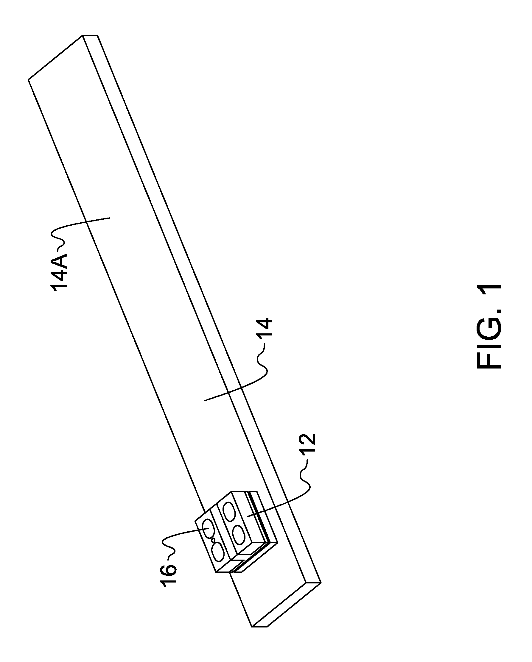
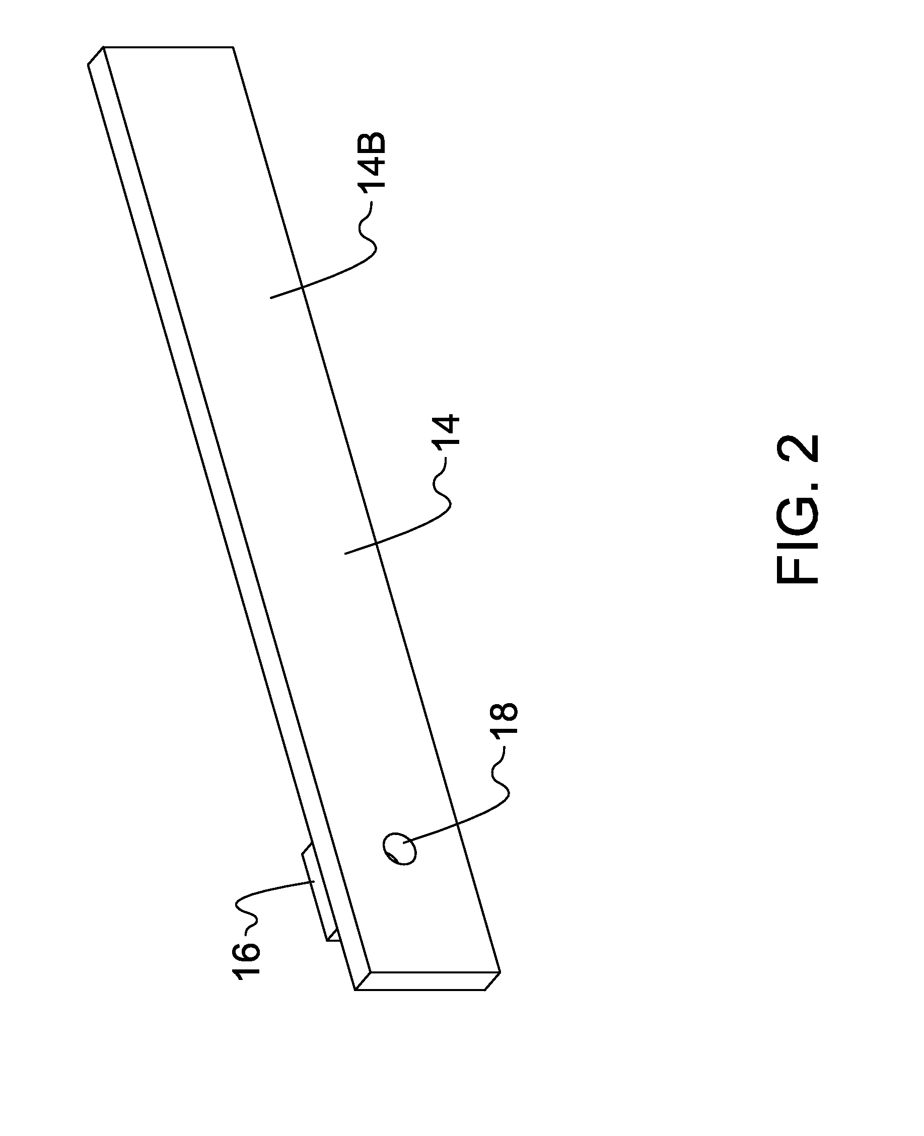
[0031]With reference to FIG. 1, there is shown in perspective view, a pressure sensor device 12 (hereinafter identified as a “pressure sensor”) mounted on an elongated base plate 14. To be discussed in more detail below, base plate 14 preferably is formed of an electrically non-conductive material such as glass. The pressure sensor 12, which is contained within a pressure sensor module 10 (see FIG. 4), may be selected from a number of commercially available silicon based pressure sensors using for example, capacitive or strain gauge pressure detecting technologies. The pressure sensor of the present invention is fabricated using micro-electro-mechanical-system or MEMS technology. Accordingly, the pressure sensors are relatively small having typical dimensions of about 2 by 2 by 1 millimeters or less. The pressure sensor of the present invention includes a pressure sensitive silicon membrane which is exposed to the environment of which the pressure is to be measured. The membrane is ...


PUM


Abstract

A hermetically sealed biocompatible pressure sensor module configured for implant at a desired site at which a pressure is to be measured. Anodic bonding of the pressure module package components which have similar thermal coefficients of expansion provides low stress bonding and maintains long term reliability, dependability and accuracy. The pressure sensor module includes a pressure sensitive membrane which is in direct contact with the environment at which a pressure is to be measured. The pressure sensor module forms a part of a pressure measuring system which uses a telemetry link between the pressure sensor module and an external controller for data transmission and transfer. Operating power for the pressure sensor module is provided by the external controller and an internal rechargeable energy storage component. Accordingly, the pressure measuring system provides a dual stage power and data transfer capability for use with an implantable system. An exemplary use of the pressure sensor module is in a three pressure sensor system including a flow control valve in a shunt to treat hydrocephalus. The use of integrated circuit chips and an internal coil with an optional ferrite core in the pressure sensor module provides for low power consumption and reliable signal processing. An embodiment of the invention includes a pressure sensor and associated electromagnetic coils embedded in the tip portion of the shunt for measuring the pressure of fluid externally of the shunt at the tip portion.

Description

CROSS REFERENCE TO RELATED APPLICATIONS[0001]The present application claims the benefit under 35 U.S.C. 119(e) of provisional application Ser. No. 61 / 443,508, entitled Pressure Sensor System for Implanted Applications, filed Feb. 16, 2011, and provisional application Ser. No. 61 / 443,535, entitled Implantable Shunt System With Multiple Pressure Sensors, filed Feb. 16, 2011, which are both incorporated herein by reference in their entirety.BACKGROUND OF THE INVENTION[0002]Pressure sensors for implantable applications have been developed in the past. A focus of the pressure sensors in the art has been to monitor, for example, intracranial pressures, intrapleural and blood pressure. Recently, particular attention has been drawn to monitor and treat a condition known as hydrocephalus. Hydrocephalus, also known as “water in the brain,” is a medical condition in which there is an abnormal accumulation of cerebrospinal fluid (CSF) in the ventricles, or cavities, of the brain. This may cause...

Claims


Application Information

Patent Timeline
Patent Type & Authority Applications(United States)
IPC IPC(8): A61B5/03
CPCA61B5/031A61B5/076A61B5/686A61M27/006A61B5/0031A61B2560/0219A61B5/6864A61B5/6865A61B5/6868H02J50/10A61N1/3787H02J50/005H02J50/40A61N1/37229
Inventor SCHMIDT, SIEGMARBYERS, CHARLES L.JIANG, GUANGQIANGDEARDEN, BRIAN R.GORD, JOHN C.RODRIGUEZ, DANIEL
Owner ALFRED E MANN FOUND FOR SCI RES
Why Eureka
Try Eureka