Apparatuses, Systems and Methods for Determining Effective Wind Speed

a technology of effective wind speed and apparatus, applied in the field of data collection, can solve problems such as problems such as problems such as problems such as implementation, and achieve the effects of improving the accuracy of low-speed and high-speed wind velocity measurements, facilitating proper radio and gps operation, and long-term reliability

Active Publication Date: 2014-09-18
HUBBELL INC
View PDF2 Cites 22 Cited by
  • Summary
  • Abstract
  • Description
  • Claims
  • Application Information

AI Technical Summary

Benefits of technology

[0029]In accordance with illustrative embodiments of the present invention, a data acquisition device is implemented as a smart clamp that holds a transmission line conductor to a high voltage insulator. A split core current transformer in the center of the clamp or near the clamp harvests approximately 5 watts (W) to power measuring and sensor circuitry. The two halves of the split core current transformer are joined during clamp installation or during a separate installation process. Communication and sensor electronics (e.g., a GPS device and radio) are housed in a non-metallic enclosure on the side of the smart clamp. The non-metallic material facilitates proper radio and GPS operation. A “T-shaped” extension at the bottom of the enclosure houses ambient air temperature and wind speed detectors. Wind measurement is done without moving parts to help assure long-term reliability, and features unique two-stage technology to improve the accuracy of low-speed and high-speed wind velocity measurements. A smart grid can be implemented using a multi-hop short range radio system to relay information between data acquisition devices provided along the line to one or two ground-based adaptors that convert the information to a standard electrical or optical Ethernet interface. Each clamp's radio has an approximate line-of-sight range of about 1 mile and is operated in accordance with a protocol for participating in multi-hop short range radio communications. Each clamp is configured to send a message (e.g., a short e-mail message) to programmable e-mail addresses in case of events such as current surges, excessi...

Problems solved by technology

This implementation, however, has proven to be problematic.
For example, routing fiber to a clamp that is operating at very high voltage creates a voltage creep path that can cause an arc even though glass fiber and plastic sheath are provided as insulators.
However, this implementation has likewise been problematic due to the complexity of the software needed to accommodate the distances over which the clamps are used and the number of clamps being monitored.
Certain Problems can Occur in Current Grids
Transmission lines face numerous problems.
Wind causes vibration which can gradually crack the wire or destroy it outright.
Excessive heat may cause lines to sag into trees or traffic.
Corroded wires will generate more heat when current passes through, but there is no way to know the extent of any corrosion since it is generally interior to the wire.
Ice buildup can break wire due to the weight.
Trees may fall naturally over wires and pose a hazard if not trimmed.
Natural and man-made disasters, such as earthquakes and forest fires can damage transmission power lines.
In addition, wildlife, and squirrels in particular, can get carbonized when they crawl into certain components of a power grid, thereby causing disruption of power transmission via the power transmission lines.
Further, environmental elements such as wind can impact low capacity of a conductor.
Line optimization to boost capacity is temperature dependent and can currently only be done via conservative estimates of local conditions due to lack of effective systems and methods for detecting the cooling effects of wind on conductors.
In addition, there is no early warning with regard to ice build-up and ice is detected when a wire breaks during icing.
Vibration dampers are routinely attached to the power lines to reduce vibration; however, their effectiveness is only estimated by how many lines break due to vibration stress, in spite of the dampers being present.
However, such cameras are large and expensive.
The cameras are generally sent to p...

Method used


Image

  • Apparatuses, Systems and Methods for  Determining Effective Wind Speed
  • Apparatuses, Systems and Methods for  Determining Effective Wind Speed
  • Apparatuses, Systems and Methods for  Determining Effective Wind Speed

Examples


Embodiment Construction

[0055]This description is provided to assist with a comprehensive understanding of illustrative embodiments of the present invention described with reference to the accompanying drawing figures. Accordingly, those of ordinary skill in the art will recognize that various changes and modifications of the illustrative embodiments described herein can be made without departing from the scope and spirit of the present invention. Also, descriptions of well-known functions and constructions are omitted for clarity and conciseness. Likewise, certain naming conventions, labels and terms as used in the context of the present disclosure are, as would be understood by skilled artisans, non-limiting and provided only for illustrative purposes to facilitate understanding of certain illustrative implementations of the embodiments of the present invention.

[0056]Data Acquisition Device Overview

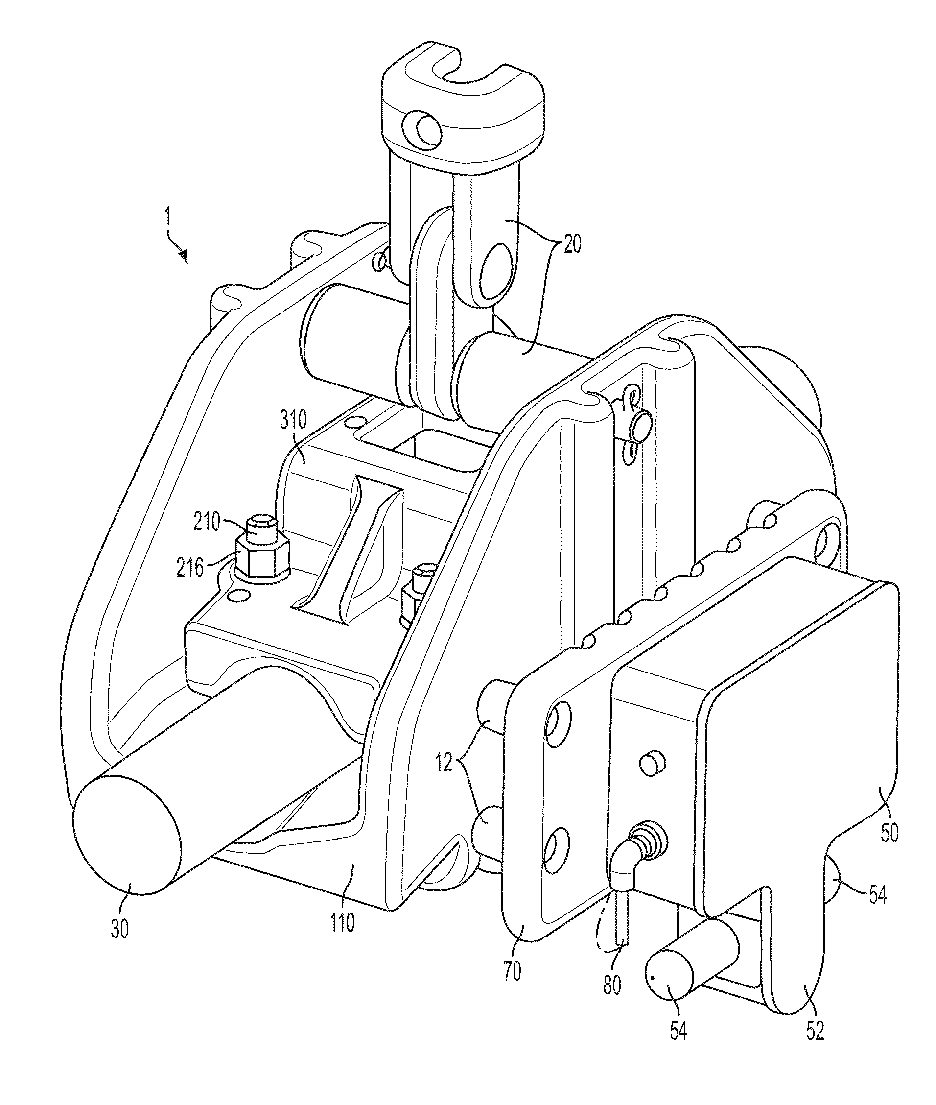
[0057]FIGS. 5-21 illustrate illustrative embodiments of the present invention that provide for a method, sy...


PUM


Abstract

Systems and methods for determining an effective wind speed are disclosed. A system includes a first detector, a second detector and a processing unit. The first detector includes a heated temperature-sensing element having a heater and a first temperature sensor, and a first housing at least partially housing the heated temperature-sensing element. The second detector includes a non-heated temperature-sensing element having a second temperature sensor, a second housing at least partially housing the non-heated temperature-sensing element. The processing unit can be adapted to determine the effective wind speed according to a temperature at the heated temperature-sensing element, a temperature at the non-heated temperature-sensing element, and/or a difference between these temperatures and in accordance with an algorithm or table of values. The heated and non-heated temperature-sensing elements and their respective first housing and second housing are collinear, proximal and parallel to the conductor, and protected from precipitation by a shield.

Description

[0001]This application claims the benefit of U.S. provisional patent application Ser. No. 61 / 781,529, filed Mar. 14, 2013, the entire disclosures of which are incorporated herein by reference.CROSS REFERENCE TO RELATED APPLICATIONS[0002]Related subject matter is disclosed and claimed in International Application PCT / US2011 / 001632, filed Sep. 22, 2011, in U.S. Patent Application Publication No. 2010 / 0151735 A1, in U.S. Patent Publication No. 2007 / 0141922 A1 and in U.S. Pat. No. 7,430,932 B2, the entire disclosures of which are also incorporated herein by reference.FIELD OF THE INVENTION[0003]The present application relates to data collecting and, more particularly, to a connector (e.g., data acquisition suspension clamp) for an electrical conductor or other transmission line (e.g., a power transmission line, a communications line, a gas line, a water line, an oil line, a railroad, a highway, among others that are deployed over geographic distances) which collects data and reports mea...

Claims


Application Information

Patent Timeline
IPC IPC(8): G01P5/10
CPCG01P5/10H02G7/04G01P1/026
Inventor MILLER, GARY MICHAEL
Owner HUBBELL INC
Why Eureka
Try Eureka