Antenna apparatus

a technology of antenna and antenna body, applied in loop antennas, electromagnetic radiation sensing, instruments, etc., can solve the problems of affecting the performance of the antenna, difficult to achieve miniaturization and thinning, large thickness of the antenna, etc., to achieve the effect of reducing or preventing significant electrode loss, facilitating the acquisition of capacitance, and further simplifying and miniaturizing the structur

Inactive Publication Date: 2014-10-02
MURATA MFG CO LTD
View PDF2 Cites 12 Cited by
  • Summary
  • Abstract
  • Description
  • Claims
  • Application Information

AI Technical Summary

Benefits of technology

[0017]Thus, a capacitance is obtained by utilizing an overlapping area between the conductive patterns of two main surfaces disposed on the antenna substrate. As a result, an additional capacitor(s) is not required, and the structure is further simplified and miniaturized. Because the capacitor of the coil antenna is obtained by utilizing the overlapping area of the conductive patterns located on two main surfaces of the a...

Problems solved by technology

However, in Japanese Patent No. 4325621, the control substrate having a feeding coil disposed thereon and the antenna substrate having a coil antenna disposed thereon are disposed on different substrates, such that the thickness thereof is large, and it is difficult to achieve miniaturi...

Method used


Image

  • Antenna apparatus
  • Antenna apparatus
  • Antenna apparatus

Examples


embodiment 1

Preferred Embodiment 1

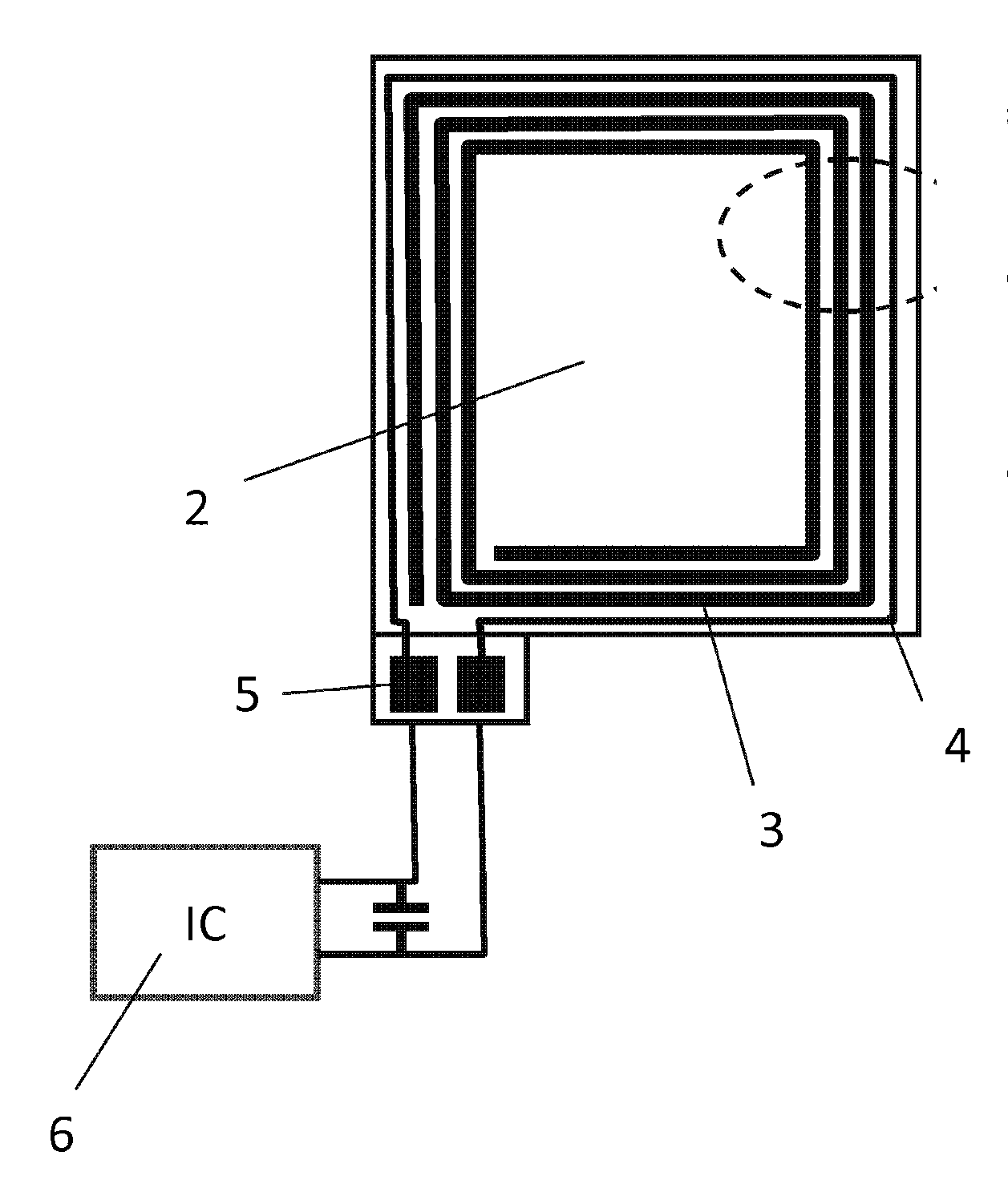
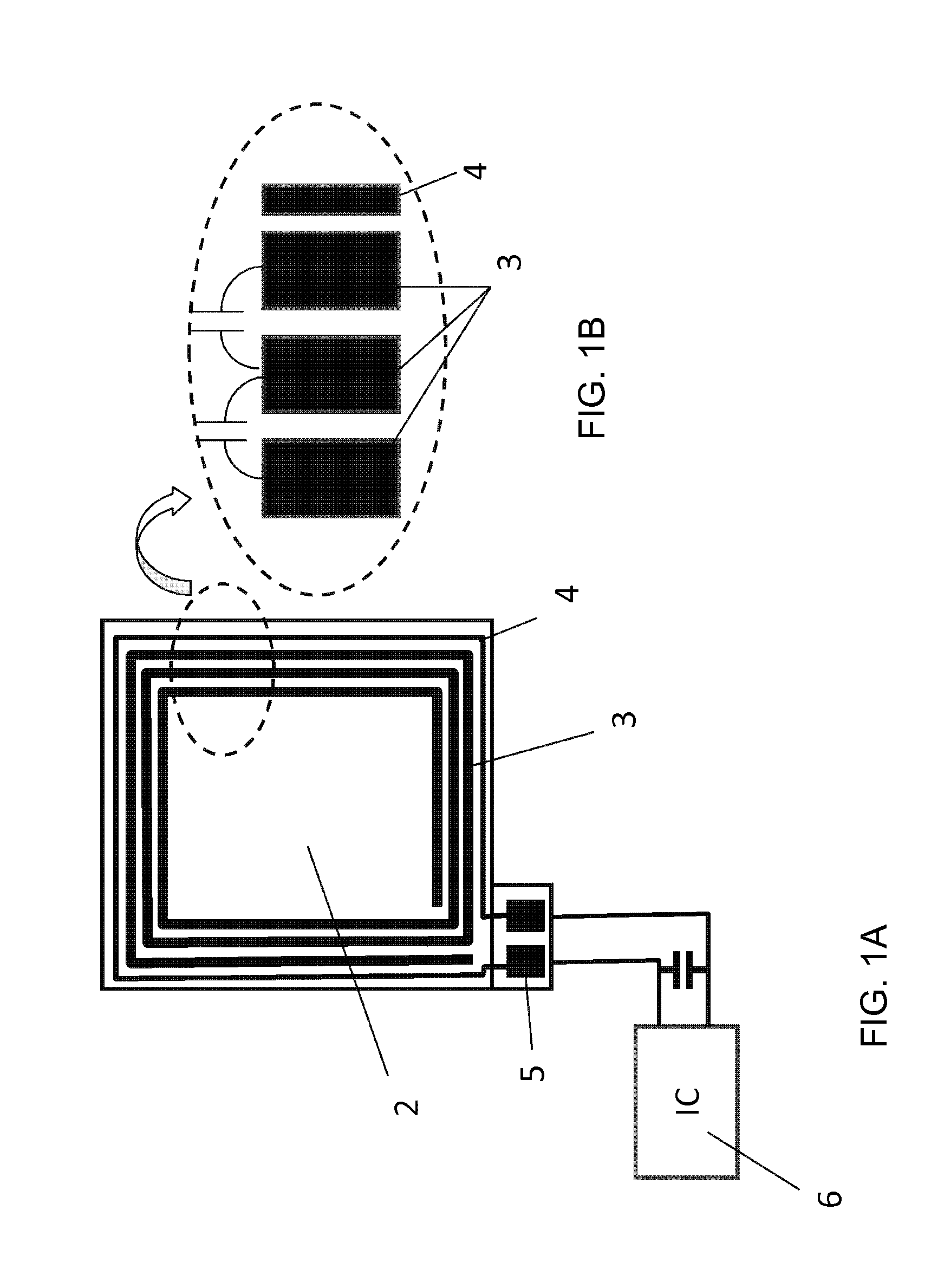
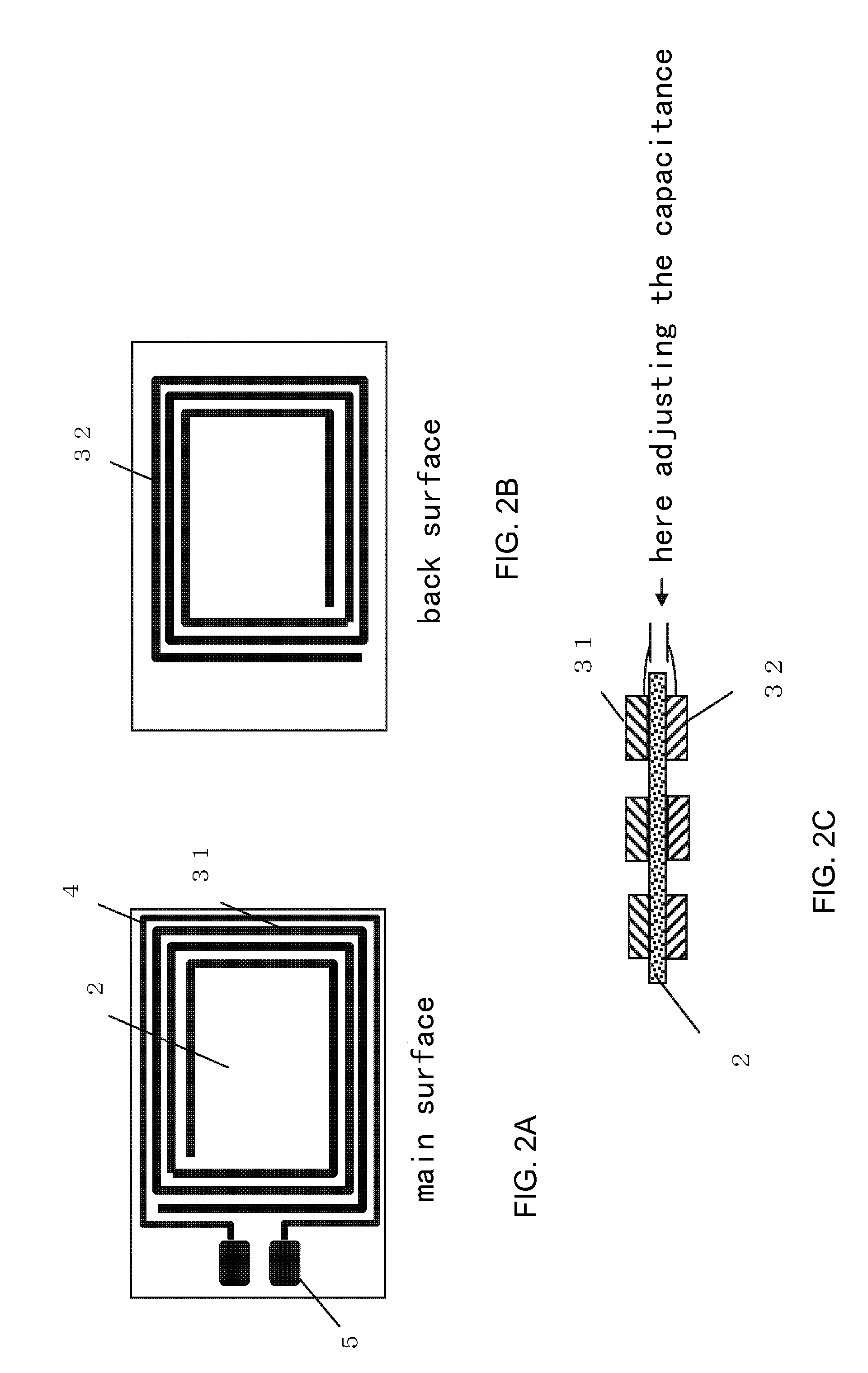
[0024]FIG. 1A is a top view of the antenna apparatus 1 according to Preferred Embodiment 1 of the present invention, and FIG. 1B is a schematic view of the amplified dash line portion of FIG. 1A, showing the relationship between the electrostatic capacitances of the coil antenna and the feeding coil. The antenna apparatus 1 according to Preferred Embodiment 1 of the present invention preferably includes an antenna substrate 2, a coil antenna 3 including a conductive pattern located on the antenna substrate 2, a feeding coil 4 magnetically coupled with the coil antenna 3, and a transceiver circuit 6 electrically connected with the feeding coil 4.

[0025]The antenna substrate 2 preferably is a PET substrate, having a rectangular or substantially rectangular planar shape, for example. The antenna substrate 2 is not limited to this; instead, for example, flexible substrates, and the like, can also be used as the antenna substrate 2.

[0026]The coil antenna 3 is provide...


PUM


Abstract

An antenna apparatus includes an antenna substrate, a coil antenna including a conductive pattern located on the antenna substrate, a feeding coil magnetically coupled with the coil antenna, and a transceiver circuit electrically connected with the feeding coil. The feeding coil is disposed on the same substrate as the coil antenna, and is defined by a conductive pattern, which is not electrically connected with the coil antenna. Two terminals of the feeding coil are electrically connected with the transceiver circuit.

Description

BACKGROUND OF THE INVENTION[0001]1. Field of the Invention[0002]The present invention relates to an antenna apparatus, and particularly, relates to an antenna apparatus preferably for use in a RFID tag or a reader-writer of HF (High Frequency) frequency band.[0003]2. Description of the Related Art[0004]RFID (Radio Frequency Identification) systems have been used as payment systems or article management systems. In an RFID system, wireless communication can be conducted between the reader-writer and the RFID tag in a non-contact manner, and high frequency signals are received and transmitted between those devices. The reader-writer and the RFID tag include IC chips used in RFID for processing high frequency signals and antennas for receiving and transmitting high frequency signals, respectively.[0005]For example, in a RFID system using an HF frequency band of 13.56 MHz, a coil antenna is used as an antenna. The coil antenna at the reader-writer side and the coil antenna at the RFID t...

Claims


Application Information

Patent Timeline
IPC IPC(8): G06K7/10G06K19/077H01Q7/00
CPCG06K7/10336G06K19/07783H01Q7/00H01Q1/2216G06K19/07794
Inventor KUBO, HIROYUKIITO, HIROMITSU
Owner MURATA MFG CO LTD
Why Eureka
Try Eureka