Eureka AIR delivers breakthrough ideas for toughest innovation challenges, trusted by R&D personnel around the world.

Optical element having a coating of high diffusivity

Active Publication Date: 2014-11-06
CARL ZEISS VISION INT GMBH
View PDF8 Cites 6 Cited by
  • Summary
  • Abstract
  • Description
  • Claims
  • Application Information

AI Technical Summary

Benefits of technology

The invention aims to prevent defects in the coating of an optical element made of plastic by ensuring the coating has high permeability to water vapor or water molecules, and low diffusivity. The scratch resistance of the coating is also improved by adding a quartz layer and microscopic or mesoscopic pores in the coating. The invention also focuses on increasing the contribution of a polar component to enhance the diffusivity of the coating. These improvements provide better protection and performance of the optical element.

Problems solved by technology

One known disadvantage of optical lenses made of plastic, however, is that their surface area is highly susceptible to mechanical stresses and can easily be damaged by scratching.
In a coating on a substrate body made of plastic, defects can arise which are initiated by the absorption of water vapor or water molecules into the substrate body if the latter comes into contact with moisture, that is water or water vapor, but also with customary cleaning media such as alcohol or acetone.
If these substances penetrate into an optical element for example on account of damage to the coating, that can have the consequence that, in the case of the optical element, the substrate body or else a layer applied thereto, such as a hard lacquer layer, for example, swells.
On account of an individual scratch location, the optical element can thus easily be damaged in this way in a region extending over one square millimeter or else a number of square millimeters.
These diffusion processes lead to local volume changes, however, which in part are irreversible.
They cause surface deformations, in particular, which, for example, not only bring about point and line patterns (warpage) on a coating, but also, in the case of spectacle lenses, can cause striations discernible to the naked eye under ambient lighting and furthermore also layer defects on account of mechanical stresses.

Method used


Image

  • Optical element having a coating of high diffusivity
  • Optical element having a coating of high diffusivity
  • Optical element having a coating of high diffusivity

Examples


Embodiment Construction

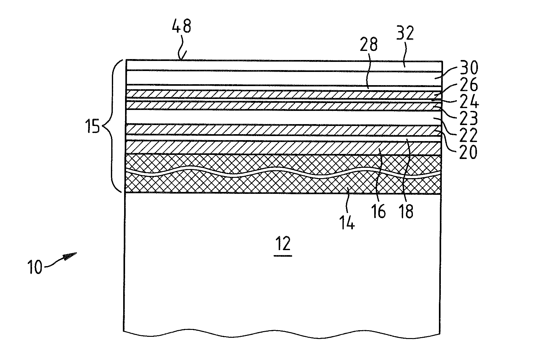
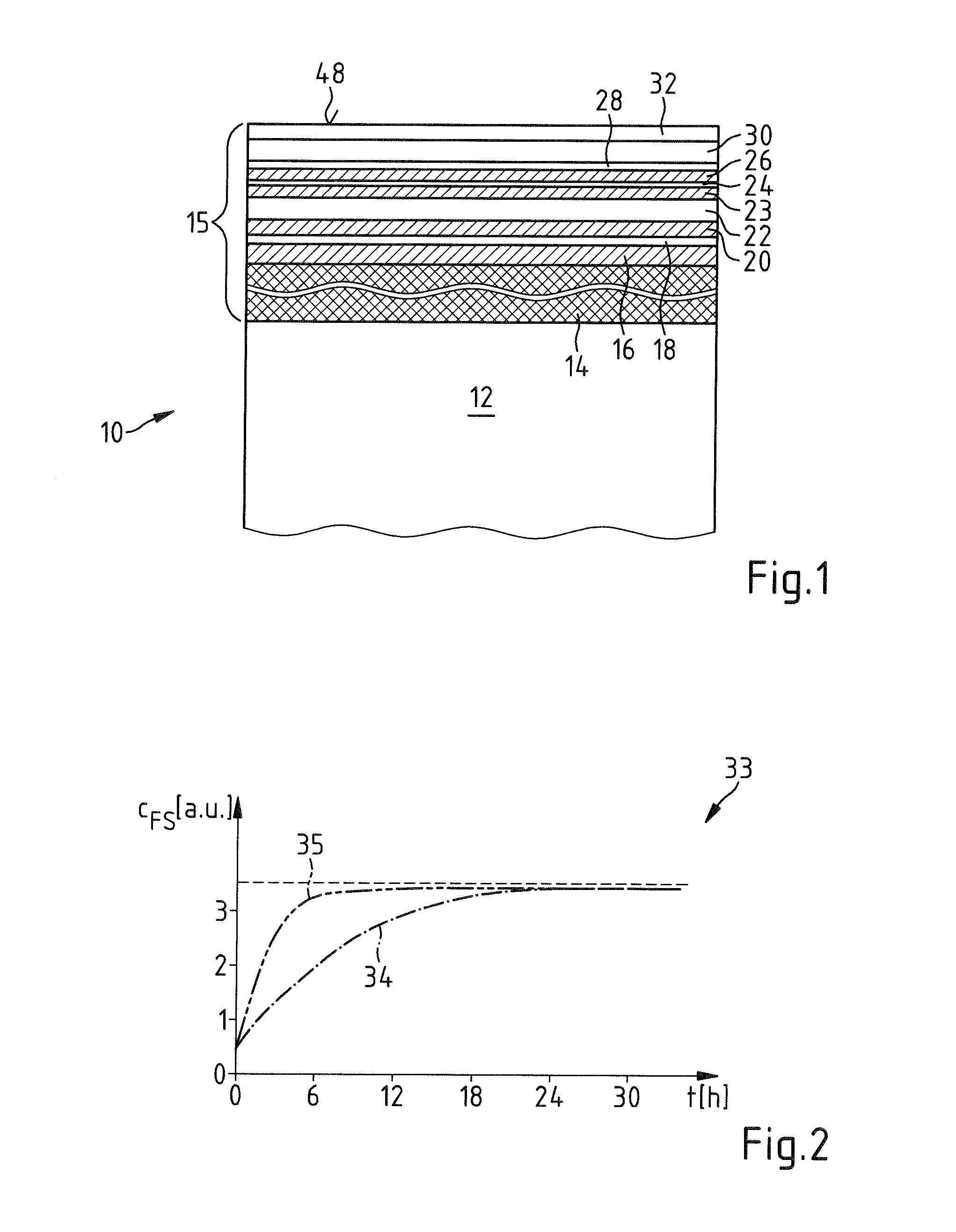
[0065]The optical element 10 shown in a partial section, which is not true to scale, in FIG. 1 has a substrate body 12 made of plastic, for example the plastic CR39. A hard lacquer layer 14 is situated on the substrate body 12 and adjoins the substrate body 12. The hard lacquer layer 14 is applied with a sol-gel hard lacquer composition that is preferably spun onto the substrate body 12 via spin coating or applied via dip coating.

[0066]On the hard lacquer layer 14 there is a coating 15 embodied as a layer stack and having an antireflection coating, which includes a plurality of partial layers, and a topcoat. This layer stack includes a layer 16 made of aluminum oxide (Al2O3) having a thickness of 57 nm, this layer being applied to the hard lacquer layer 14. A 25 nm thick layer 18 made of quartz (SiO2) is situated on the layer 16. A further layer 20 made of aluminum oxide, the thickness of which is 44 nm, lies above the layer 18. The layer 20 is followed by a 61 nm thick further laye...


PUM

PropertyMeasurementUnit
Temperatureaaaaaaaaaa
Timeaaaaaaaaaa

Abstract

An optical element has a substrate body made from transparent plastic and a coating having multiple layers. The coating includes a hard lacquer layer adjoining the substrate. The coating has a diffusivity ensuring the absorption of water molecules passing through the coating in the substrate and the release of water molecules from the substrate through the coating from an air atmosphere on that side of the coating facing away from the substrate with a flow density which, proceeding from the equilibrium state of the quantity of water molecules absorbed in the substrate in an air atmosphere at 23° C. and 50% relative humidity, brings the setting of the equilibrium state of the quantity of water molecules absorbed in the substrate in an air atmosphere at 40° C. and 95% relative humidity within an interval not more than 10 h longer than for setting this equilibrium under corresponding conditions with an identical uncoated substrate.

Description

CROSS REFERENCE TO RELATED APPLICATION[0001]This application claims priority of German patent application no. 10 2013 208 310.6, filed May 6, 2013, the entire content of which is incorporated herein by reference.FIELD OF THE INVENTION[0002]The invention relates to an optical element, in particular a spectacle lens or a spectacle lens blank, including a substrate body made from a plastic, which is transparent preferably in the visible spectral range, and including a coating having a plurality of layers. The coating includes a hard lacquer layer adjoining the substrate body.BACKGROUND OF THE INVENTION[0003]An optical element of this type is known in the form of an optical lens embodied as a spectacle lens for example from United States patent application publication 2012 / 0081792.[0004]For optical lenses, in particular for spectacle lenses, plastic that is transparent in the visible spectral range is increasingly being used nowadays as material instead of silicate glass. Compared with ...

Claims


Application Information

Patent Timeline
IPC IPC(8): G02C7/02
CPCG02C7/02G02B1/12G02C7/022G02B1/113G02B1/14B29D11/00009B29D11/00865B29D11/00432G02B1/11
Inventor HUGENBERG, NORBERTHAIDL, MARKUSVON BLANCKENHAGEN, BERNHARDHOLZ, LOTHARKRAUS, STEFANMACIONCZYK, FRANKKRAUSE, MICHAELGREEN, ERWINWINTER, KARL-HEINZGLOEGE, THOMASFAUL, SILVIAPETEREIT, ANJAPENG, BINPUETZ, JOERGKIEFER, PATRICKHANSSEN, ADALBERTKRIEGER, MICHAELNEUFFER, ANDREASSTROISCH, MARC
Owner CARL ZEISS VISION INT GMBH
Why Eureka
Eureka Blog
Learn More