
Devices and Systems to Mitigate Traumatic Brain and Other Injuries Caused by Concussive or Blast Forces

a technology of brain injury, applied in the field of devices and systems to mitigate brain injury caused by concussive or blast force, can solve the problems of limited ability to increase intercranial volume, reduce the differential acceleration between the skull and its contents, etc., to reduce intracranial compliance, prevent concussions or damage to the structures within the cranium, and increase cerebral blood volum

Active Publication Date: 2014-11-20
TBI INNOVATIONS +1
View PDF5 Cites 51 Cited by
  • Summary
  • Abstract
  • Description
  • Claims
  • Application Information

AI Technical Summary

Benefits of technology

The patent describes a method to protect the brain from serious injuries caused by concussive forces. By compressing a vein in the neck, the method increases the volume of blood in the brain and reduces the compliance of the skull. This reduces the risk of damage to the brain, vascular tissues, inner ear, spinal column, and eye. This method, in addition to traditional helmets, can provide better protection against concussions and damage to the brain.

Problems solved by technology

Although headgear is effective in preventing the most devastating intracranial injuries, penetrating injuries, and skull fractures, it is limited in its ability to prevent concussions or damage to the structures within the cranium.
This results in increased intercranial volume and resultant pressure and thus reduction of the differential acceleration between the skull and its contents when subjected to a concussive force.
In some related embodiments, restriction of the blood flow egressing from the head of the subject results in an increase in fluid volume and pressure in the intracranial cavity of the subject.

Method used


Image

  • Devices and Systems to Mitigate Traumatic Brain and Other Injuries Caused by Concussive or Blast Forces
  • Devices and Systems to Mitigate Traumatic Brain and Other Injuries Caused by Concussive or Blast Forces
  • Devices and Systems to Mitigate Traumatic Brain and Other Injuries Caused by Concussive or Blast Forces

Examples


example 1

Materials and Methods

[0193]Two groups of ten (total of 20) male Sprague-Dawley rats weighing between 350 and 400 grams were used. Animals were housed under 12 hour light / 12 hour dark conditions with rat chow and water available ad libitum.

[0194]Marmarou Impact Acceleration Injury Model in Rats:

[0195]Anesthesia was induced and maintained with isoflurane using a modified medical anesthesia machine. Body temperature was controlled during the approximately 10 min. procedures using a homeothermic heating blanket with rectal probe, and adequate sedation was confirmed by evaluation of response to heel tendon pinch. The animals were shaved and prepared in sterile fashion for surgery, followed by subcutaneous injection of 1% lidocaine local anesthetic into the planned incision site. A 3 cm midline incision in the scalp was made and periosteal membranes separated, exposing bregma and lambda. A metal disk 10 mm in diameter and 3 mm thick was attached to the skull with cyanoacrylate and centere...

example 2

Experimental Protocol

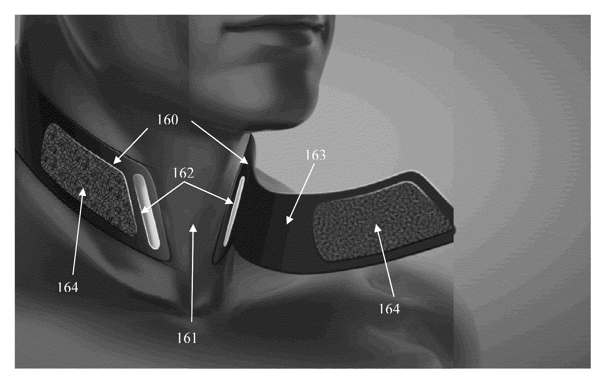
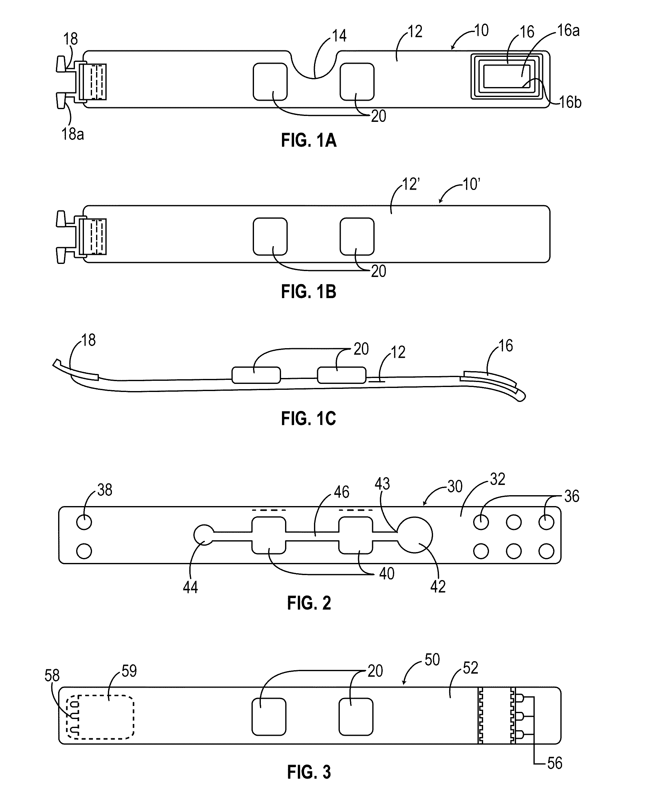
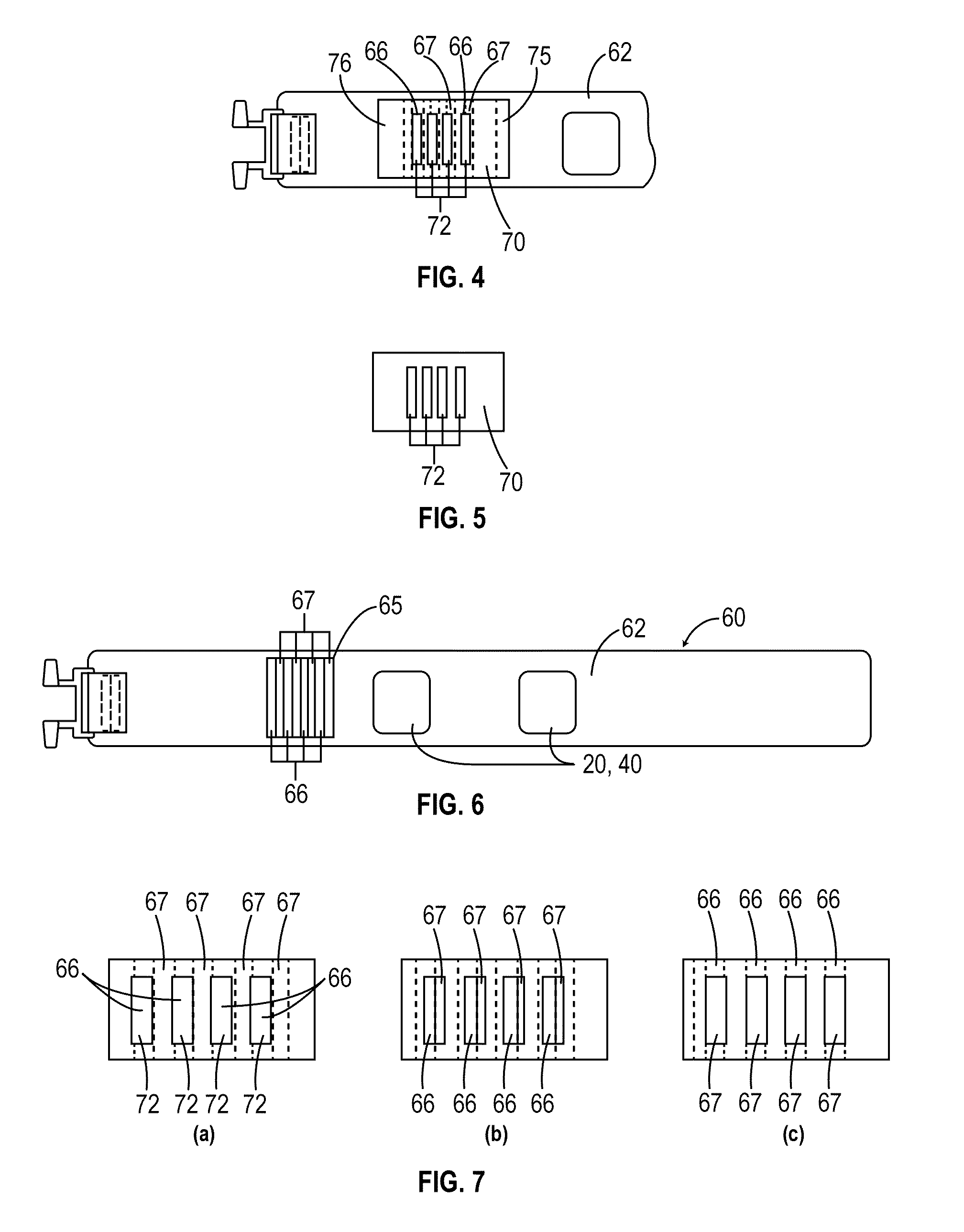
[0197]This work involved two groups, each consisting of 10 animals for a total of 20 animals. Two groups were utilized, a control injury group and an experimental injury group. In the experimental injury group the rats were fitted with a 15 mm wide collar, with two compressive beads designed to overlay the IJVs and was tightened sufficiently to provide mild compression of the veins without compromising the airway. The collar was then fixed in circumference with a Velcro fastener. The collar was left in position for three minutes prior to administrating experimental brain injury.

[0198]Assessment of Intracranial Reserve Volume Intracranial Pressure (ICP) Measurement:

[0199]ICP was measured in five animals using the FOP-MIV pressure sensor (FISO Technologies, Quebec, Canada) as described by Chavko, et al. The head of the rat was shaved and prepped in sterile fashion for surgery. The rat was fixed in a stereotaxic apparatus (model962; Dual Ultra Precise Small Animal ...

example 3

Volume Intracranial Pressure (ICP) Measurement

[0209]ICP was assessed both prior to and after application of the IJV compression device. The baseline ICP was 10.23±1.68 mm Hg and was increased to 16.63±2.00 mm Hg following IJV compression (FIG. 8: p<0.01). Notably, this increase of greater than 30% from baseline occurred within seconds following IJV compression. Intraocular Pressure (IOP) Measurement: IOP measurements were taken both before and after application of the IJV compression device, similar to ICP recordings. The baseline IOP was 11.18±2.27 mm Hg and was elevated to 16.27±3.20 mm Hg following IJV compression (FIG. 9: p<0.01).

[0210]The increase of 31% seen in IOP following IJV compression is strikingly similar to that seen in ICP following IJV compression, both in magnitude and rapidity of response (FIG. 10).

[0211]TBI-Impact Acceleration Model:

[0212]None of the animals died from the head trauma. Animals tolerated collar application without any observed untoward effects for t...


PUM


Abstract

A system for reducing the damaging effects of radiant energy, blast, or concussive events includes applying pressure to at least one jugular vein to reduce the egress of blood from the cranial cavity during or before the incidence of the imparting event. Reducing blood outflow from the cranial cavity increases intracranial volume and / or pressure of the cerebrospinal fluid to reduce the risk of traumatic brain injury and injuries to the spinal column. Reducing blood outflow further increases the intracranial pressure and volume, and thereby increases the pressure and volume of the cochlear fluid, the vitreous humor and the cerebrospinal fluid to thereby reduce the risk of injury to the inner ear, internal structure of the eye and of the spinal column. In addition, increasing intracranial pressure and volume reduces the likelihood of brain injury and any associated loss of olfactory function

Description

CROSS-REFERENCE TO RELATED APPLICATIONS[0001]This patent is a continuation-in-part of U.S. Ser. No. 13 / 842,273, filed on Mar. 15, 2013, which is a continuation in part of U.S. Ser. No. 13 / 489,536, filed Jun. 6, 2012, which is a continuation-in-part of U.S. Ser. No. 12 / 931,415, filed Feb. 1, 2011, which is a continuation-in-part of U.S. Ser. No. 12 / 807,677, filed Sep. 10, 2010, which claims the benefit of U.S. Provisional Applications 61 / 260,313, filed Nov. 11, 2009, and 61 / 241,625, filed Sep. 11, 2009. U.S. Ser. No. 13 / 489,536 is also a continuation-in-part of International Application PCT / US2011 / 055783, filed Oct. 11, 2011, which claims the benefit of U.S. Provisional Application 61 / 518,117, filed Apr. 29, 2011. Each of the above-referenced patent applications is incorporated herein by reference.TECHNICAL FIELD[0002]The present disclosure is generally related to systems for reducing the effects of exposure to concussive events.BACKGROUND OF THE INVENTION[0003]Traumatic brain injury...

Claims


Application Information

Patent Timeline
IPC IPC(8): A61B17/132A61H39/04A61B17/135
CPCA61B17/1325A61H39/04A61B17/1327A61B17/135A61B17/132A61B2017/00017A61B2017/00221F41H1/00A61B2017/00778
Inventor SMITH, DAVID W.VITITOE, KEVIN JOHNFLOAT, JAMISON JOSEPHLEEDER, CHAD MICHAELFISHER, JOSEPH A.STITES, JOHN
Owner TBI INNOVATIONS
Learn More