
Method for preparing r-fe-b based sintered magnet

a sintered magnet and fe-b technology, applied in the field of preparing r — fe — b based sintered magnets, can solve the problems of complex process, low yield, and complicated method operation, and achieve low production cost, high yield, and simple operation

Active Publication Date: 2014-12-04
YANTAI ZHENGHAI MAGNETIC MATERIAL CO LTD
View PDF9 Cites 17 Cited by
  • Summary
  • Abstract
  • Description
  • Claims
  • Application Information

AI Technical Summary

Benefits of technology

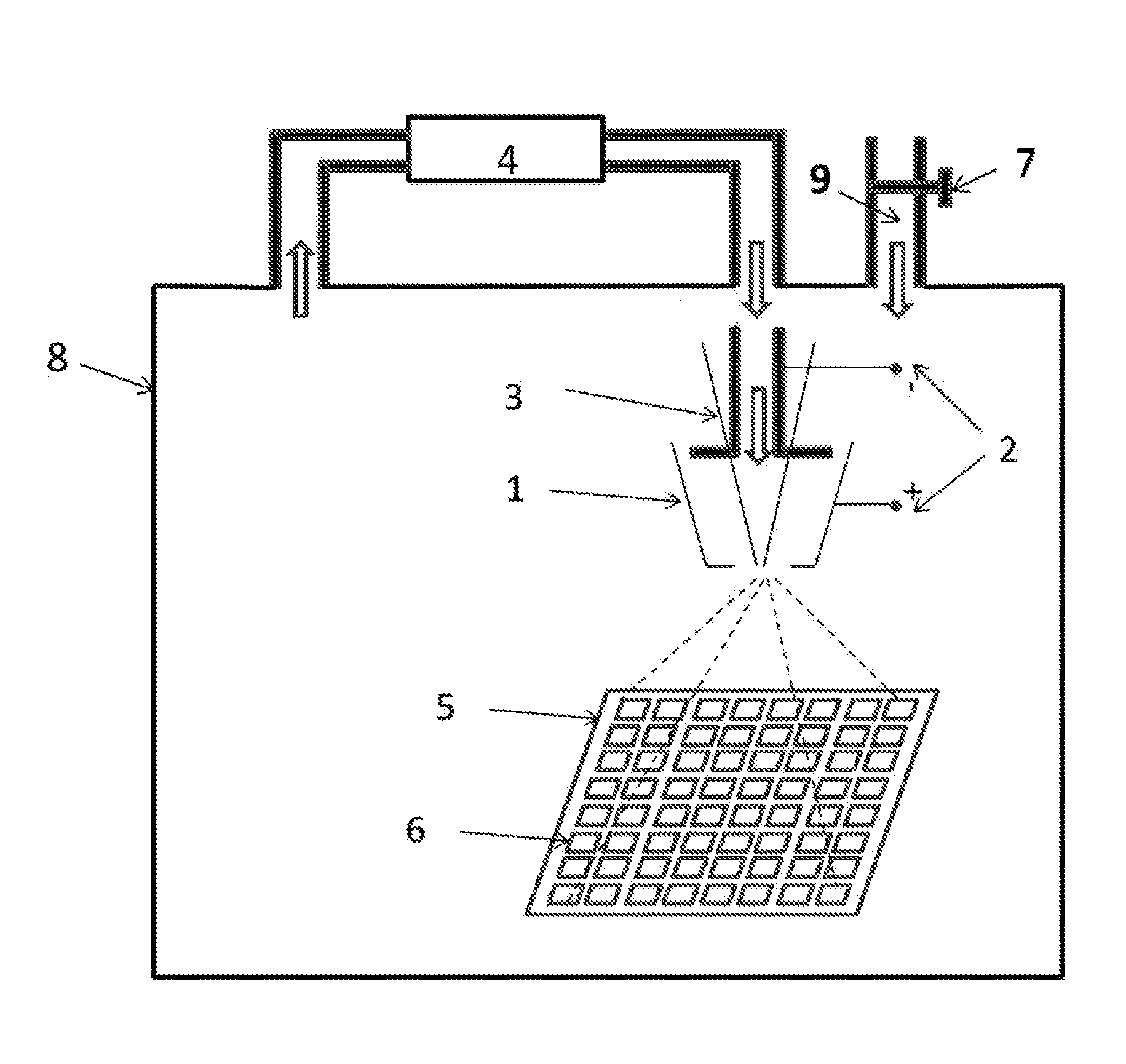
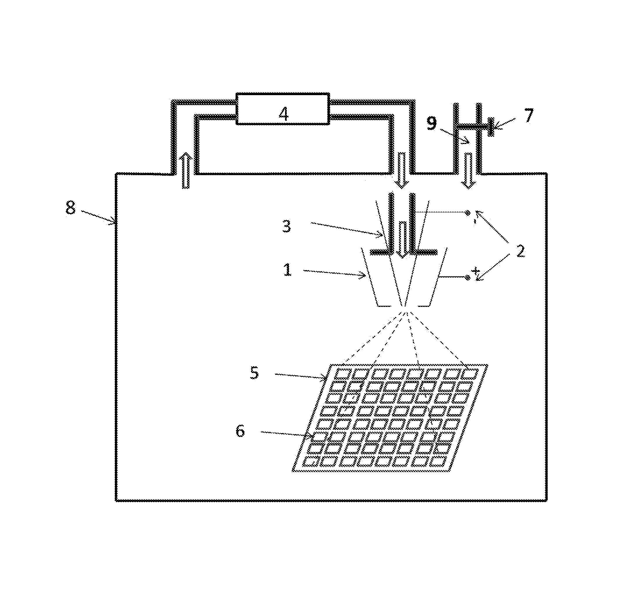
The invention provides a method for making an R-Fe-B based sintered magnet with improved performance. By coating a layer of Tb or Dy on the surface of the magnet using hot spraying, and then heating it to allow the coated material to enter the magnet by grain boundary diffusion, the coercivity of the magnet is significantly improved. Compared to other methods, this process is easier and more efficient, resulting in high yields with no need for washing after treatment. The method also has good appearance and practical significance.

Problems solved by technology

The method has a complicate operation, a large amount of Tb or Dy powder is attached to the magnet piece after treatment, which requires further machining or washing for removal.
The process is complicate and easily results in waste.
Besides, the slurry coated on the surface of the magnet is still in the form of powder after being dried, thereby being easily falling off, and the increase of the coercivity of the magnet after treatment is not dramatic.
However, a distance exists between the magnet to be treated and the evaporation source, so that the space utilization is decreased and the production cost of the treatment is relatively high.
Because the diffusion of the heavy rare earth elements to the inner part of the sintered magnet is on the premise that the grain boundary is melted at the high temperature, whereas Pr and Nd in the melted grain boundary are easily replaced by the heavy rare earth elements, so that the sintered magnet and the heavy rare earth elements or alloy are easily stuck together once the movement is not in time, thereby being poorly practical.

Method used


Image

  • Method for preparing r-fe-b based sintered magnet
  • Method for preparing r-fe-b based sintered magnet

Examples


example 1

[0035]A mixture was prepared that comprised 23.8 wt. % of Nd, 5 wt. % of Pr, 0.6 wt. % of Dy, 0.4 wt. % of Tb, 68.29 wt. % of Fe, 0.5 wt. % of Co, 0.13 wt. % of Cu, 0.1 wt. % of Ga, 0.1 wt. % of Al, 0.12 wt. % of Zr, and 1 wt. % of B. The mixture was poured in a vacuum melting furnace under an atmosphere of an inactive gas, a pouring temperature was controlled at 1450° C., and a rotational speed of a quenching roller was 60 rpm, so that flakes having a thickness of 0.3 mm were formed. The flakes were pulverized by hydrogen decrepitation and jet milling to yield powder with an average particle size of 3.5 μm. The power was compressed under a 15 KOe magnetic field to form a compact. The compact was then placed in a sintered furnace under an Ar atmosphere and sintered at the temperature of 1100° C. for 5 hrs to obtain a green body. Thereafter, the green body was aged at the temperature of 500° C. for 5 hrs to obtain a sintered blank. The sintered blank is then machined to form magnet p...

example 2

[0038]The method for preparing 50 M magnet piece was the same as that in Example 1 that includes melting, pulverizing, pressing, heating, and wire cutting. The 50 M sintered magnet (40 mm*20 mm*4 mm) was degreased, washed by acid, activated, washed by deionized water, and desiccated, respectively. 20 pieces*10 pieces of sintered magnets were placed in a hot spraying sealed box and the surface of each sintered magnet was hot sprayed with a layer of Tb having a thickness of 20 μm on one side thereof, the sintered magnet was then turned over in a glove box, and the other side of the sintered magnet was hot sprayed with another layer of Tb having a thickness of 20 μm. The sintered magnet after the hot spraying treatment was transferred to a vacuum sintering furnace, maintained at the temperature of 945° C. under an Ar pressure of 5 kPa for 48 hrs, and then aged for 5 hrs at the temperature of 500° C. After that, the vacuum sintering furnace was charged with Ar to be cooled to the room t...

example 3

[0040]The method for preparing 50 M magnet piece was the same as that in Example 1 that includes melting, pulverizing, pressing, heating, and wire cutting. The 50M sintered magnet (40 mm*20 mm*4 mm) was degreased, washed by acid, activated, washed by deionized water, and desiccated, respectively. 20 pieces*10 pieces of sintered magnets were placed in a hot spraying sealed box and the surface of each sintered magnet was hot sprayed with a layer of Dy having a thickness of 20 μm on one side thereof, the sintered magnet was then turned over in a glove box, and the other side of the sintered magnet was hot sprayed with another layer of Dy having a thickness of 20 μm. The sintered magnet after the hot spraying treatment was transferred to a vacuum sintering furnace, maintained at the temperature of 930° C. for 24 hrs, and then aged for 5 hrs at the temperature of 500° C. After that, the vacuum sintering furnace was charged with Ar to be cooled to the room temperature. A firedoor of the v...


PUM

PropertyMeasurementUnit
thicknessaaaaaaaaaa
thicknessaaaaaaaaaa
temperatureaaaaaaaaaa

Abstract

A method for preparing an R—Fe—B based sintered magnet, including: preparing a R1—Fe—B-M sintered magnet having a thickness of between 1 and 10 mm; spraying a layer of Tb or Dy having a thickness of between 10 and 200 μm on each surface of the sintered magnet in a sealed box under an Ar atmosphere by hot spraying method; and transferring the sintered magnet coated with the layer of Tb or Dy to a vacuum sintering furnace, heating the sintered magnet at the temperature of between 750 and 1000° C. in a vacuum condition or under the Ar atmosphere, and allowing heavy rare earth element Tb or Dy to enter an inner part of the sintered magnet via grain boundary diffusion.

Description

CROSS-REFERENCE TO RELATED APPLICATIONS[0001]Pursuant to 35 U.S.C. §119 and the Paris Convention Treaty, this application claims the benefit of Chinese Patent Application No. 201310209231.9 filed May 30, 2013, the contents of which are incorporated herein by reference. Inquiries from the public to applicants or assignees concerning this document or the related applications should be directed to: Matthias Scholl P.C., Attn.: Dr. Matthias Scholl Esq., 14781 Memorial Drive, Suite 1319, Houston, Tex. 77079.BACKGROUND OF THE INVENTION[0002]1. Field of the Invention[0003]The invention relates to a method for preparing R—Fe—B based sintered magnet.[0004]2. Description of the Related Art[0005]R—Fe—B rare earth sintered magnet has been fast developed and widely applied to the field of the computer hard disk, hybrid power automobile, medical, and wind power generation industries due to its high strength, excellent magnetic properties, and low cost.[0006]Coercivity is a significant index for m...

Claims


Application Information

Patent Timeline
Patent Type & Authority Applications(United States)
IPC IPC(8): H01F41/00B22F3/26H01F41/02
CPCH01F41/005B22F2003/248B22F3/26H01F41/02H01F1/0577H01F41/0293C22C33/0278B22F2998/10B22F2999/00C22C2202/02C22C38/002C22C38/005C22C38/06C22C38/10C22C38/14C22C38/16B22F3/10B22F2201/20B22F2003/242
Inventor YU, YONGJIANGSUN, XIUYANLI, ZHIQIANGWANG, YULINLIU, LEI
Owner YANTAI ZHENGHAI MAGNETIC MATERIAL CO LTD
Learn More