
Process and system for capturing carbon dioxide from a gas stream

a technology of gas stream and carbon dioxide, which is applied in the field of gas stream carbon dioxide capture, can solve the problems of slow conversion of metal silicates to metal carbonates, inability of occurring sinks to effectively keep up with the vast quantities, and difficulty in recovering ammonia

Inactive Publication Date: 2014-12-04
HUNWICK RICHARD J
View PDF0 Cites 13 Cited by
  • Summary
  • Abstract
  • Description
  • Claims
  • Application Information

AI Technical Summary

Benefits of technology

The patent describes a way to prevent clogging of a reactor and to clean a slurry. The solution is to use an ammonium salt that doesn't form a precipitate with metal silicate. This ammonium salt can be mixed with other salts like ammonium sulphate or ammonium nitrate, which can be by-products of a process to remove carbon dioxide from power plant emissions. The system also includes a stage to make ammonium chloride to replace any minor losses that may occur during the process.

Problems solved by technology

However, these naturally occurring sinks are not capable of effectively keeping up with the vast quantities of carbon dioxide being produced in today's power-thirsty climate.
In addition, insoluble metal carbonates formed during the key carbonation reaction may act to coat and hence passivate the surfaces of the metal silicate rock particles and thereby slow the conversion of metal silicates to metal carbonates.
In addition, where the conversion of metal silicates to carbonates plus silica in the pipeline or other reactor is incomplete, the recovery of ammonia is rendered more difficult because the thermal processes used can cause substantial production of carbon dioxide from the decomposition of unreacted ammonium carbonate / bicarbonate.

Method used


Image

  • Process and system for capturing carbon dioxide from a gas stream
  • Process and system for capturing carbon dioxide from a gas stream
  • Process and system for capturing carbon dioxide from a gas stream

Examples


Embodiment Construction

[0078]In the following description, embodiments of the process and system are described in the context of capture of carbon dioxide contained within flue gases emitted by a fossil fuel-fired power station. However, it is to be understood that the process and system may equally be employed for the capture of carbon dioxide from any ‘point’ source and are not limited to the particular arrangements described herein.

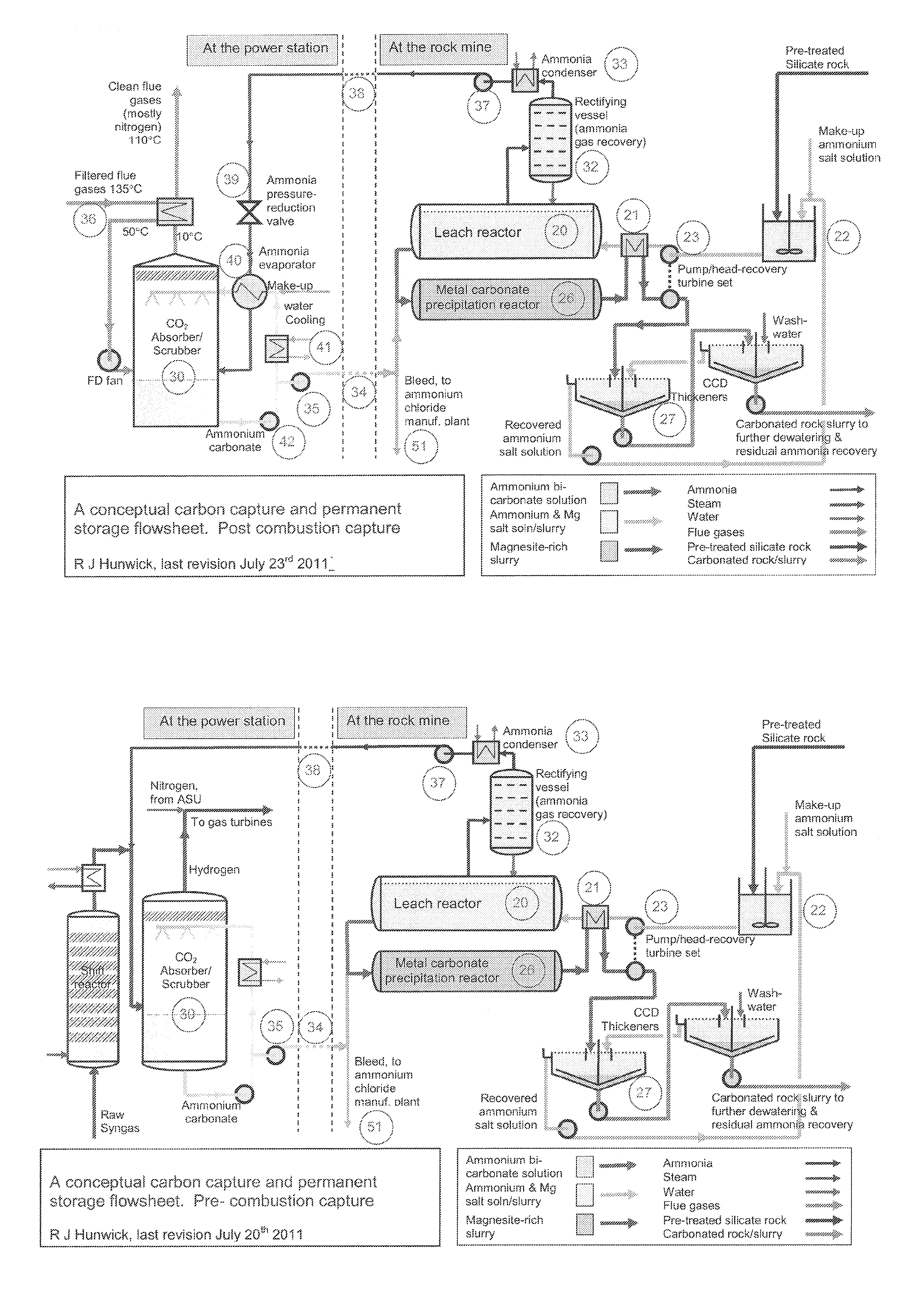
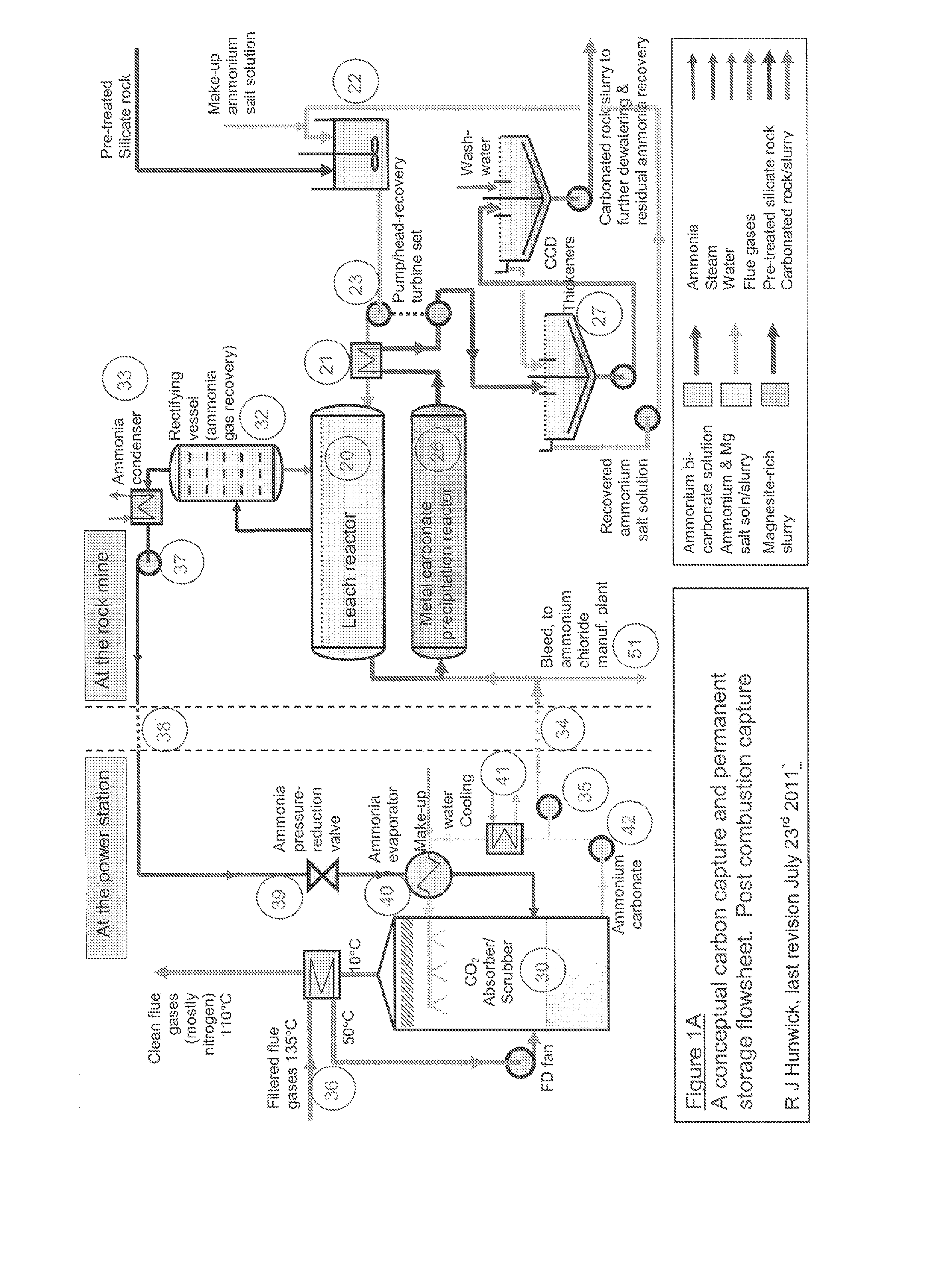
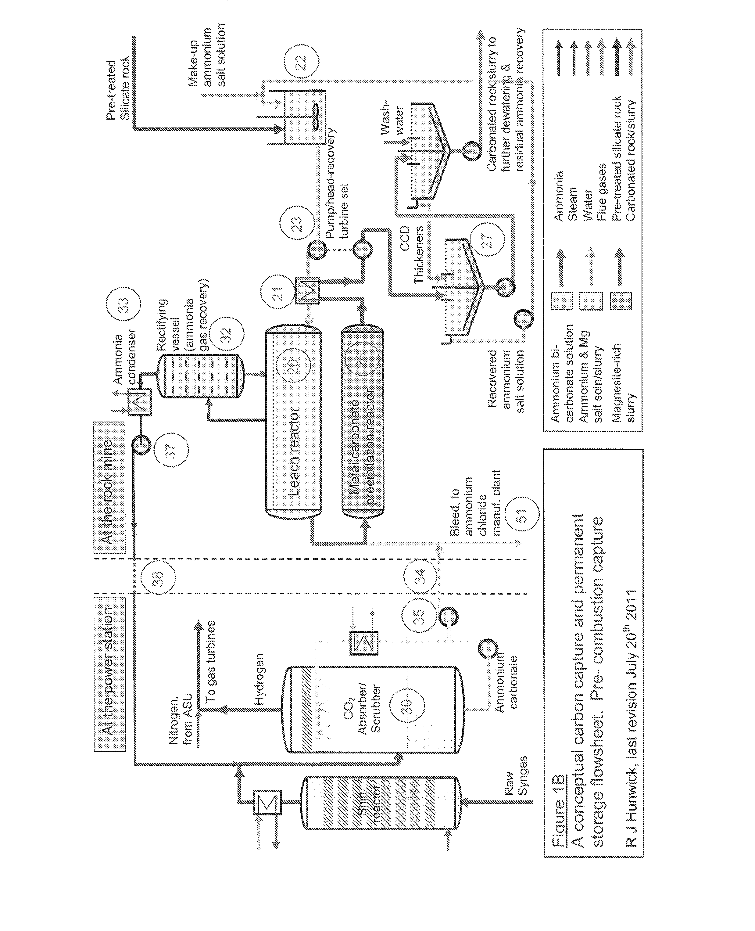
[0079]With reference to FIG. 1A there is shown a flow diagram of a System 10 for performing a carbon dioxide (CO2) capture process from a gas feed stream containing carbon dioxide outputted from a power station, in accordance with a first embodiment. The embodiment depicted in FIG. 1B differs from the flow diagram shown in FIG. 1A in that the gas feed stream is at an elevated pressure (e.g. 25 Bar gauge). Such may occur with gas feed streams gas stream produced by a water gas shift reactor (e.g. that has been fed with syngas, or a stream of raw natural gas that is contaminat...


PUM

PropertyMeasurementUnit
Temperatureaaaaaaaaaa
Pressureaaaaaaaaaa
Boiling pointaaaaaaaaaa

Abstract

A process and system are disclosed for capturing carbon dioxide from a gas stream. The process and system comprises a first reactor in which a slurry of a metal silicate is reacted together with an ammonium salt in aqueous solution. The salt is one that does not form a precipitate with the metal silicate. In the first reactor the metal silicate reacts with the solution to produce a slurry of silica in an aqueous solution of a salt of the metal and ammonia. Ammonia gas is drawn off directly from the first reactor, and ammonia, including the ammonia drawn off from the first reactor, is added to the gas stream. The process and system also comprises scrubbing the gas stream, including with the added ammonia, with an aqueous solution, whereby the carbon dioxide and ammonia are absorbed into the solution and ammonium carbonate salt(s) are produced.

Description

TECHNICAL FIELD[0001]A process and system are disclosed for capturing carbon dioxide from a gas stream. The gas stream may originate as flue gas from coal-fired power stations or may originate from other point sources such as power stations fired by other fossil fuels including natural gas, as well as steel mills, cement plants and other industrial sites including oil and metal refineries, or from the burning of other fuels containing carbon including biomass-derived fuels such as alcohols, agricultural residues and biogas.BACKGROUND ART[0002]There is increased focus on reducing carbon dioxide emissions to the atmosphere, to help minimise the effects of global warming. Carbon dioxide sinks exist naturally, including the weathering of silicate rocks to form carbonates, and the world's oceans. Plants are also an effective form of carbon dioxide sink and use photosynthesis to remove carbon from the atmosphere by incorporating it into biomass. However, these naturally occurring sinks ar...

Claims


Application Information

Patent Timeline
IPC IPC(8): B01D53/96B01D53/62C01B32/50C01B32/60
CPCB01D53/62B01D53/96B01D53/80B01D2251/108B01D2251/206B01D2251/2062B01D2251/304B01D2251/604B01D2258/0233B01D2258/025B01D2258/0283B82Y30/00B82Y40/00C01C1/26C01D7/123C01D7/26Y02P20/151Y02C20/40
Inventor HUNWICK, RICHARD J.
Owner HUNWICK RICHARD J
Learn More