
Centrifugal separator with Anti-fouling properties

a centrifugal separator and anti-fouling technology, applied in centrifuges and other directions, can solve the problems of increasing reducing the flow capacity, and requiring a higher speed to achieve the same separation performance, so as to reduce the risk of clogging the separation passage, the effect of reducing the formation of cracks

Inactive Publication Date: 2014-12-18
ALFA LAVAL CORP AB
View PDF4 Cites 1 Cited by
  • Summary
  • Abstract
  • Description
  • Claims
  • Application Information

AI Technical Summary

Benefits of technology

The invention provides an improved centrifugal separator with reduced fouling and wear-resistant in abrasive environments. The separator has a high resistance against formation of cracks. The coating composition applied to the disc surfaces using sol-gel material with organosilicon compounds significantly lowers the surface free energy and roughness, reducing fouling and easy cleaning. The low layer thickness of the coating allows for high separation performance without increasing the risk of clogging the separation passages. The invention improves the efficiency and performance of the centrifugal separators.

Problems solved by technology

The ability to provide a layer thickness of the coating that is significantly less than the disc thickness, i.e. tens of μm compared to hundreds of μm, the coating does not result in any significant reduction of the height of the separation passage, which otherwise could lead to reduced flow capacity, requiring higher speed to obtain the same separation performance, and increased risk of clogging the separation passages.
Either way, the separation performance would be detrimentally affected, either by restricting the flow through the separation passages, or reducing the total separation area through a reduction in the number of discs.

Method used


Image

  • Centrifugal separator with Anti-fouling properties
  • Centrifugal separator with Anti-fouling properties
  • Centrifugal separator with Anti-fouling properties

Examples


examples

[0041]In the search for prolonged operational time of off-shore equipment, tests were conducted on low surface energy glass ceramic coatings of which both are of the type of coating described above. The coatings are referred to as Coat 1 and Coat 2, the results are presented below. Coat 1 is a silan terminated polymer in butyl acetate and Coat 2 is a polysiloxan-urethan resin in solvent naphtha / butylacetate.

[0042]The tests were performed on coated heat transfer plates. Such plates are provided in heat exchangers that may be used in a process line also containing continuous operation centrifugal separators. In other words, the media coming into contact with the heat transfer plates is often the same media that later in the process is to be separated in a centrifugal separation process. Thus, the tests performed on heat transfer plate surfaces of a heat exchanger to obtain anti-fouling characteristics for the coating may also be useful indicators for a coating on a disc surface within...


PUM


Abstract

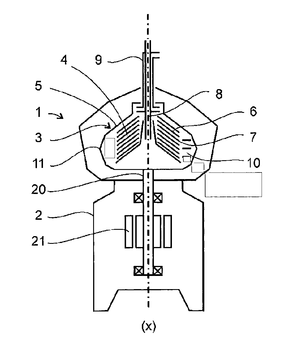
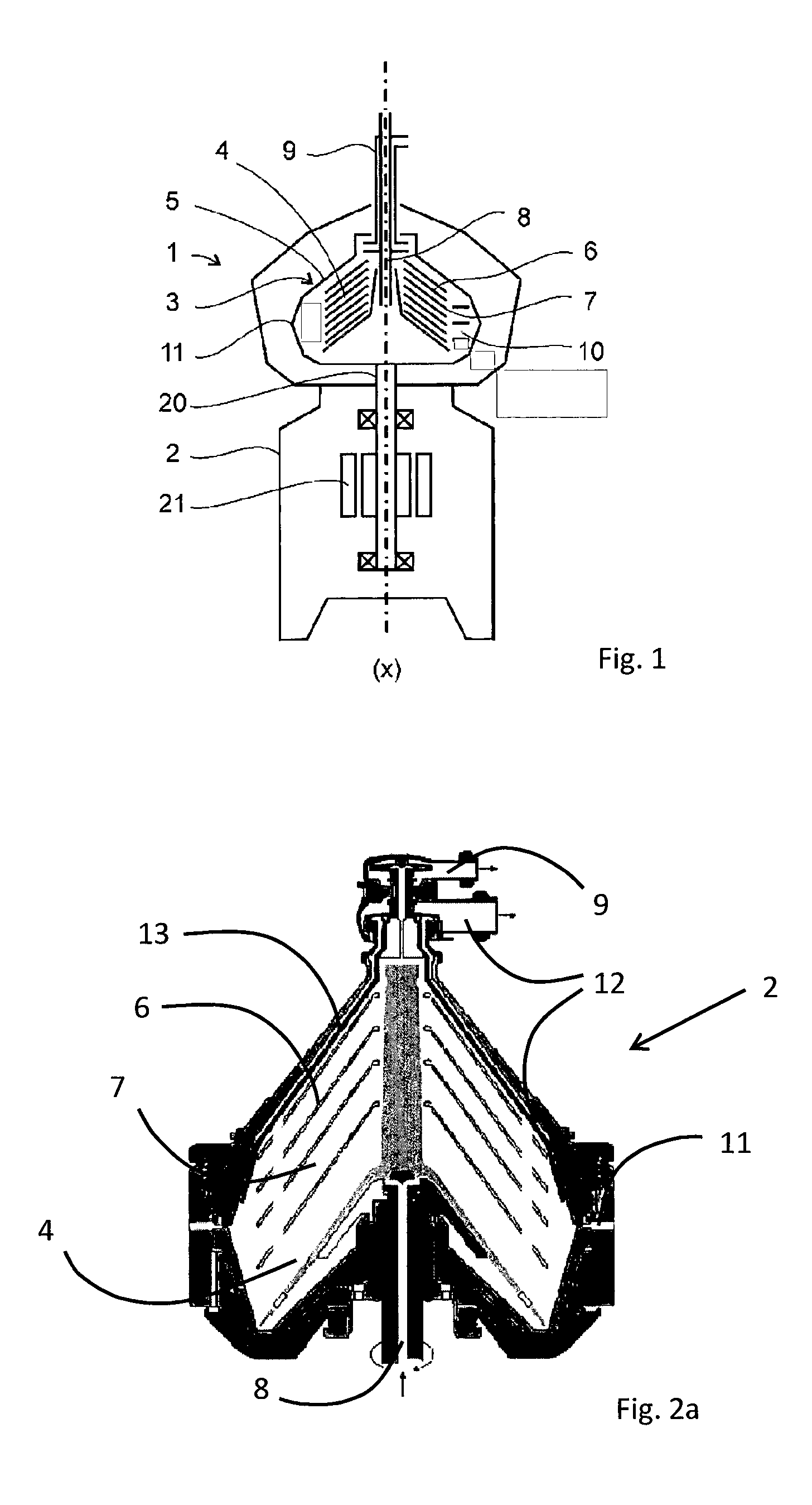
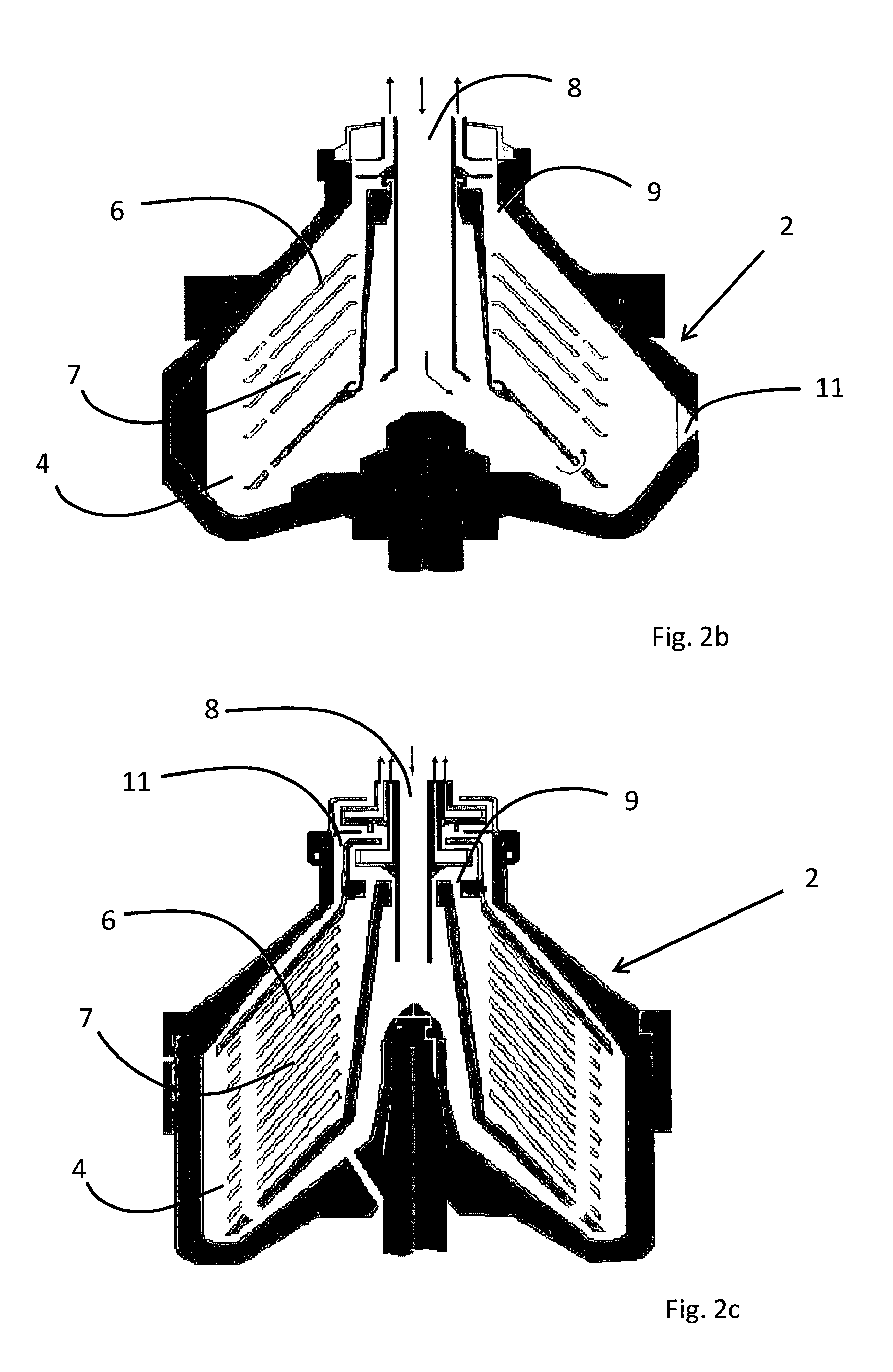
A centrifugal separator for continuous separation of a fluid mixture into components includes a rotor, which forms within itself a separation chamber, including in said separation chamber a set of separation discs defining separation passages between adjacent separation discs. The separator further includes an inlet operatively connected to said rotor for continuous supply of a fluid mixture to be separated in the separation chamber, a first outlet for a separated lighter first component of the fluid mixture extending from a radially inner portion of the separation space, and a second outlet for a separated denser second component of the fluid mixture extending from the radially outer portion of the separation space. The separation discs are provided with a coating including silicon oxide, SiOx, prepared through sol-gel processing.

Description

TECHNICAL FIELD[0001]The present invention relates to a centrifugal separator according to the preamble of claim 1 which has been coated for improving anti-fouling properties.BACKGROUND ART[0002]Fouling is a generally known problem within centrifugal separators. During operation, fouling of e.g. separator discs, frame and sludge outlet channels is of concern, for example due to deposits, microbial growth, dirt etc. that arise from the fluids that pass through the centrifugal separator. In particular, fouling of the separator discs may reduce the throughput rate of the separator if its separation capability is to remain unchanged. Furthermore, deposits formed on the separator discs may have to be removed periodically, i.e. the discs and the interior of the separator being cleaned. In a separator arranged for continuous throughput, stoppages for removing deposits results in undesired downtime of the separator and, consequently, a reduced overall separation capacity.[0003]In modern cen...

Claims


Application Information

Patent Timeline
IPC IPC(8): B04B15/06B04B7/08
CPCB04B7/08B04B15/06B04B7/14
Inventor NILSSON, MATSANEHAMRE, JONASSZEPESSY, STEFANMANELIUS, TOM
Owner ALFA LAVAL CORP AB
Learn More