Column Buffer Thermal Energy Storage

a thermal energy storage and buffer technology, applied in the field of thermal energy, can solve the problems of not being watertight, not designed to resist water pressure, and the approach cannot be retrofitted to existing buildings without rebuilding

Inactive Publication Date: 2015-01-08
KAWANO KEGAN NOBUYSHI
View PDF8 Cites 15 Cited by
  • Summary
  • Abstract
  • Description
  • Claims
  • Application Information

AI Technical Summary

Benefits of technology

[0029]The liner may cover the sides and bottom of the at least one opening. The liner may be formed from at least on

Problems solved by technology

They do not store temperature differences, are not designed to have tight thermal coupling with the surrounding earth, are not watertight and are not designed to resist water pressure when completely filled with liquid.
This approach cannot be retrofitted to existing buildings without rebuilding.
The existing Passive Annual Heat Storage (PAHS) approach does store heat between seasons, but cannot be retrofitted to an existing building.
Although these technologies do store temperature differences across seasons, they are not generally used for active storage across seasons.
At minimum, these technologies all suffer the disadvantage that PEX tubing is thermally insulative and retards heat exchange with the surroundings.
This requires larger and more costly installations for the same thermal capacity.
Leaks in the pressurized tubing can damage the heat pump and the environment, are very costly, disruptive, and time consuming to repair.
Large open surface areas are required to install the long trenches, so this is generally not an option in urban areas.
Much disruption is done to the surface because of the trench and the trenching machinery.
Tubes are run in parallel or helical configurations causing reduced efficiency due to parasitic heat leakage between parallel tubes or points where helical coils cross each other.
In both cases, a long period of time occurs where soil heat capacity and conductivity are reduced due to uncompacted soil.
This parasitic heat loss reduces efficiency of heat transfer with the ground.
The annular tube configuration requires specialized and more costly tubing with specialized end to transfer liquid between the inner and outer tubes.
They cannot be practically retrofit to existing buildings as pilings are integral to building engineering.
Additionally, thermal pilings are nearly impossible to repair tubing leaks as pilings support building.
These solutions are limited to environments proximate to a large body of water and may have ecological effects by changing temperature of the body of water.
Leaks in tubing may have ecological effects due to harmful components of heat exchange fluid.
Refrigerant tubes are costly.
Leaks in the tubes are very damaging to the heat pump and the environment, and very costly, disruptive and time consuming to repair.
Anti-corrosion coatings often reduce thermal conductivity, making heat transfer to earth less efficient.
ATES is not

Method used


Image

  • Column Buffer Thermal Energy Storage
  • Column Buffer Thermal Energy Storage
  • Column Buffer Thermal Energy Storage

Examples


first embodiment

[0084]This section outlines the invention.

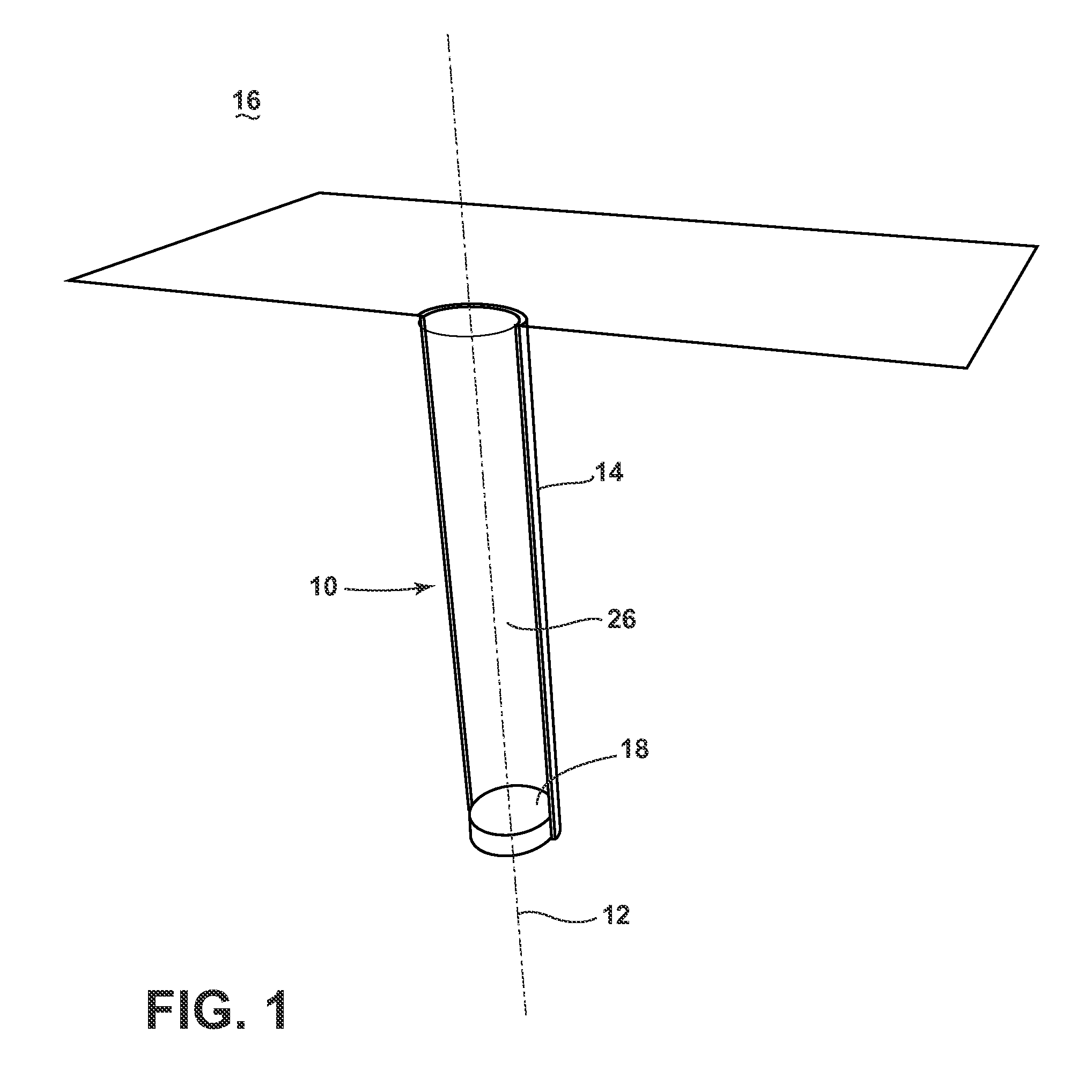
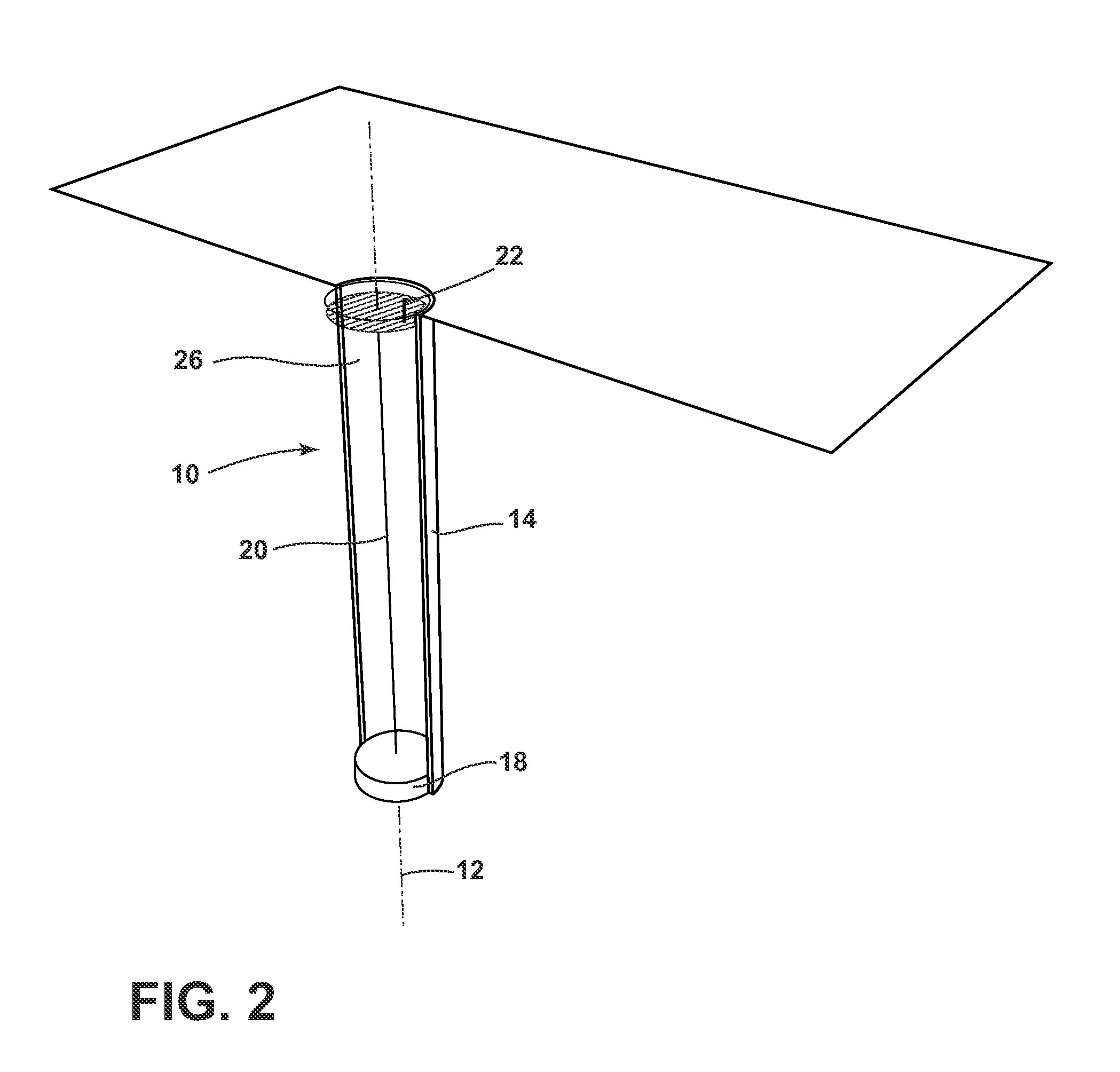
[0085]This embodiment describes a waterproof column 10 excavated into the earth as show in FIG. 1. As per the previous definition of a column, columns of many shapes are possible. Columns which change shape as one proceeds along the axis 12 are also possible. This preferred embodiment describes a column 10 which is a cylinder while not excluding other shapes previously described. The cylinder is preferred as the circular cross section provides the greatest hoop strength against both inward and outward forces. Additionally, the circular cross section allows the use of centrifugally cast concrete application technology to easily form cylindrical walls 14 strongly mated to the excavated earth walls. The circular cross section also allows the strongest geometry when placing reinforcing materials like basalt twine that reinforce against forces acting outwards on the column walls 14.

[0086]The inner diameter of the column 10 shown in FIG. 1 may ran...

second embodiment

[0095]This section outlines the invention.

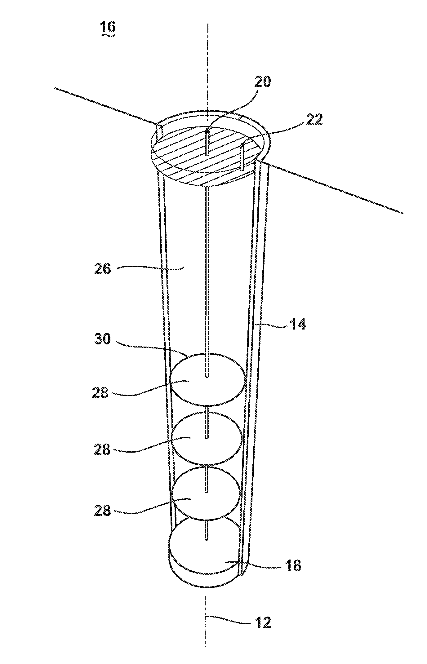
[0096]This embodiment contains all the elements of the first embodiment, but adds a series of heat stratification baffles 28 as shown in FIG. 5. The baffles 28 are constructed to be several inches smaller in diameter than the column diameter allowing a space for liquid 26 to pass between the baffle edge 30 and the column's inner surface. Due to fluid properties, a slow moving liquid film will form on the interface between the heat storage fluid 26 and the inner surface of the column walls 14. Warm fluid will tend to rise, but, all else being equal, will rise through the central axis 12 of the column 10. The heat stratification baffles 28 force this rising water past the inner surface of the column walls 14, increasing heat transfer by increased temperature and forced mixing of the liquid film. The baffles 28 may be made of many rigid, waterproof materials including, but not limited to corrugated plastic sheet, plastic, metal, and wood. The p...

third embodiment

[0097]This section outlines the invention.

[0098]This embodiment contains all the elements of the second embodiment, but adds spacers 32 to the outer edges 30 of the heat stratification baffles 28 as shown in FIG. 6. The spacers 32 keep the baffles 28 from occluding liquid movement from a large section of one side of the column as may happen when the baffles 28 rest on that side. Occluded sections will have lower heat transfer due to lower fluid movement. The spacers32 greatly reduce the occlusion. Spacers 32 may be formed from, but not limited to notches in the baffle material and material inserted in the edges 30 of the baffles 28. The preferred embodiment of spacer formation is notches in the baffle material is this is simplest and reduces manufacturing time. The preferred spacer formation embodiment does not exclude other spacer formations as previously described.

[0099]This section outlines a fourth embodiment of the invention.

[0100]This embodiment contains all the elements of th...


PUM


Abstract

A system for storing thermal energy includes an opening into the earth, a liner positioned within and surrounding an interior periphery of the opening, a liquid provided within the liner, a first conduit fluidly associated with an upper portion of the opening, a second conduit fluidly associated with a lower portion of the opening, a fluid movement device and a heat transfer device. The fluid movement device is fluidly connected between the first and second conduits and configured to transport liquid between the first and second conduits. The heat transfer device is fluidly connected to the first conduit and the second conduit and configured to transfer heat to or from the liquid.

Description

CROSS-REFERENCE TO RELATED APPLICATIONS[0001]This application claims priority to U.S. Provisional Patent Application Ser. No. 61 / 842,046, filed Jul. 2, 2013, which is incorporated herein by reference.FIELD OF THE INVENTION[0002]The invention is in the field of thermal energy and, in particular systems, for storing thermal energy.BACKGROUND OF THE INVENTION[0003]Thermal energy storage for regulating the temperature of interior building environments includes many diverse technologies. The following is a partial list of the prior art thermal energy storage technologies and a subset of shortcomings of each item on the list. It will be obvious to those with ordinary skill in the art that each list item has many more shortcomings so, for brevity, only a few shortcomings are listed. Other advantages of the present invention over the prior art also will be rendered evident in the detailed description below.[0004]Hand dug wells are structures dug in the earth to access groundwater. They do n...

Claims


Application Information

Patent Timeline
IPC IPC(8): F24J3/08H02K7/18E21D5/01F24V50/00
CPCF24J3/086F24J2003/088H02K7/1815E21D5/01E21B43/10F24T10/10F24T10/30F24T2010/53F28D20/0052Y02E10/10Y02E60/14
Inventor KAWANO, KEGAN NOBUYSHI
Owner KAWANO KEGAN NOBUYSHI
Why Eureka
Try Eureka